


Page2of4 67317-X (en)
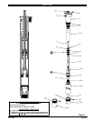
PARTS LIST
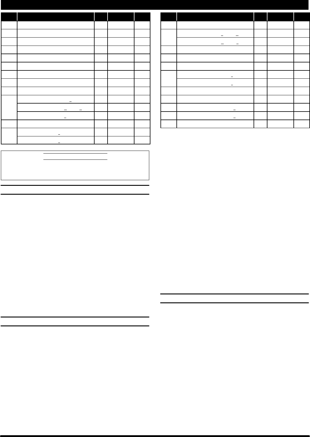
Item Description (size) Qty Part No. [Mtl] Item Description (size) Qty Part No. [Mtl]
n 1 “O” Ring (1/8” x 11/16” o.d.) (1) Y327-205 [V]
2 Pipe Plug (1/8 - 27 N.P.T.F. x 0.27”) (1) Y17-50 [C]
3 Outlet Body (1) 95705 [SS]
4 Ground Screw (#10 - 32 x 1/4”) (1) 93005 [C]
6 Inner Tube (1) 95712 [SS]
7 Rod (1) 96063 [C]
8 Dowel Pin (3/16” o.d. x 7/8”) (1) 95803 [C]
9 Retainer (1) 95804 [SH]
10 Washer (2) 95234-1 [PPS]
n 11 Rod Seal models 6731X-731 (1) 95574-2 [T]
models 6731X-B31 and -C31 (1) 95574-1 [UH]
models 6731X-J31 (1) 95235 [U]
12 Retaining Ring (0.575” i.d.) (1) 95711 [SH]
13 Rod models 67317-X (18.000” long) (1) 95710 [SS]
models 67318-X (5.500” long) (1) 95713 [SS]
14 Cup Follower (1) 90601 [SS]
n 15 Cup models 6731X-731 and -B31 (1) 73919 [T]
models 6731X-C31 and -J31 (1) 92867-1 [UH]
16 Washer (1) 90610 [SS]
17 Ball (1.000” dia.) (1) 90948 [SS]
18 Inner Check Seat (1) 96144 [SS]
19 Suction Tube models 67317-X (1) 95706 [SS]
models 67318-X (1) 95714 [SS]
21 Ball (1.1875” dia.) (1) 90949 [SS]
22 Dowel Pin (0.25” o.d. x 1.828”) (1) 90620 [SS]
23 Foot Valve Seat (models 67317-X only) (1) 95977 [SS]
24 Foot Valve Seat (models 67318-X only) (1) 96015 [SS]
n Items included in Service Kit 637379-X31
MATERIAL CODE
[C] = Carbon Steel [T] = PTFE
[PPS] = Polyphenylene Sulfide [U] = Polyurethane
[SH] = Hardened Stainless Steel [UH] = UHMW-PE
[SS] = Stainless Steel [V] = VitonR
LOWER PUMP DISASSEMBLY
NOTE: All threads are right hand.
1. Clamp (3) outlet body horizontally in a vise. Using a strap type
wrench to hold (19) suction tube, unthread and remove (23 or 24)
foot valve seat.
2. Remove (22) dowel pin, releasing (21) ball.
3. Using a strap type wrench, unthread and remove (19) suction tube.
4. Remove (13) rod and components from (19) suction tube.
5. Using a 1-1/2” wrench, unthread and remove (18) inner check seat,
releasing (17) ball, (16) washer and (15) cup.
6. Slide (12) retaining ring, (10) washers, (11) rod seal and (9) retainer
down (13) rod, allowing removal of (8) dowel pin.
7. Remove (7) rod, (9) retainer, two (10) washers, (11) rod seal and
(12) retaining ring from (13) rod.
8. Remove (1) “O” ring from (3) outlet body.
9. DO NOT remove (6) inner tube unless damage is evident. To re-
move, clamp (3)outlet body in avise and unthread (6)inner tube us-
ing a strap type wrench.
LOWER PUMP REASSEMBLY
NOTE: Refer to the illustration (figure 2, page 3) for lip seal direction.
NOTE: All threads are right hand. Thoroughly clean and lubricate all
seals and bores with Wet-Sol “Plus” upon assembly.
1. Assemble (15) cup, (16) washer and (17) ball to (14) cup follower,
securing with(18) inner checkseat. NOTE: Tighten (18)innercheck
seat to 60 - 70 ft lbs (81.3 - 94.9 Nm).
2. Assemble (14) cup follower and components to (13) rod. NOTE:
Tighten (14) cup follower to 60 - 70 ft lbs (81.3 - 94.9 Nm).
3. Slide (12) retaining ring, (10) washer, (11) rod seal (lips down), (10)
washer and (9) retainer onto top end of (13) rod, past the retaining
ring groove.
4. Assemble (7) rod to (13) rod, securing with (8) dowel pin.
5. Slide (9) retainer, (10) washer, (11) rod seal, (10) washer and (12)
retaining ring up, securing (8) dowel pin.
6. Clamp (3) outlet body horizontally in a vise.
7. Apply PTFE tape to 1-7/16” threadsof(3) outlet body and assemble
(6) inner tube to (3) outlet body. NOTE: Tighten (6) inner tube to120
in. lbs (13.6 Nm) minimum.
8. Assemble (1) “O” ring into (3) outlet body.
9. Assemble (7) rod and components into (6) inner tube and (3) outlet
body.
10. Assemble (21) ball to (23 or 24) foot valve seat, securing with (22)
dowel pin.
11. Apply PTFE tape to threads of (23 or 24) foot valve seat and as-
semble (23 or 24) foot valve seat and components to (19) suction
tube. NOTE: Tighten (23 or 24)foot valve seat to 60 -70 ft lbs (81.3 -
94.9 Nm).
12. Apply PTFE tape to threads of (3) outlet body and assemble (19)
suctiontubeto(3) outletbody.NOTE: Tighten (19)suction tubeto60
- 70 ft lbs (81.3 - 94.9 Nm).
TROUBLE SHOOTING
•
No material at outlet (pump continually cycles). Check material
supply,disconnect or shut off theairsupply and replenishthe materi-
al, reconnect.
• Material ononestroke only(fast downstroke).The (21)lower ball
may not be seating in the (23 or 24) foot valve seat. Remove the (21)
ball from the footvalve seat,clean and inspectthe balland seat area.
If the ball or seat is damaged, replace.
• Material on one stroke only (fast upstroke). The (17) upper ball
may notbe seatingin the(18) innercheck seat. Remove the (17)ball
from the (18) check seat, clean and inspect. If the (17) ball is dam-
aged, replace. Check for worn or damaged packings and seals. Re-
place the packings and seals as necessary.
S VitonR is registered trademarks ofthe DuPont Company SAROR is aregistered trademark of Ingersoll-Rand Company S