


Page 3 of 467165-X
67277-( ) SOLENOID KIT INSTALLATION
2” & 3” METALLIC DIAPHRAGM PUMPS
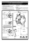
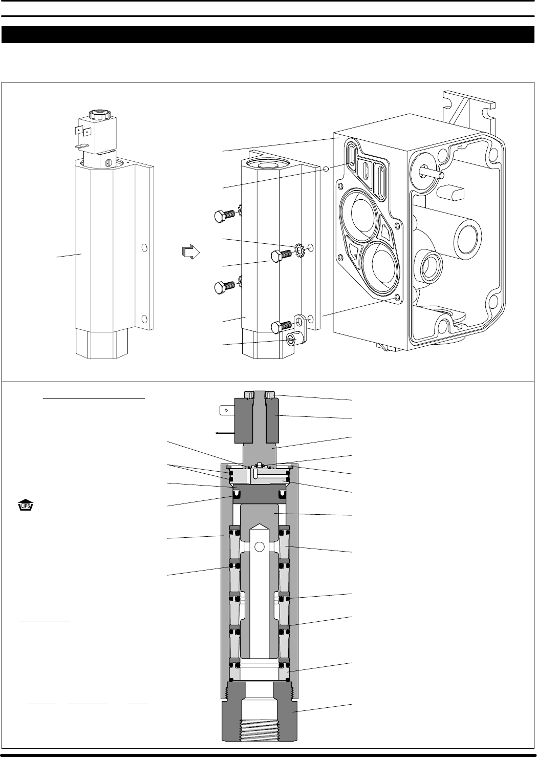
Refer to figure 3.
1. Remove (134) screws and (133) washers, and remove (135) valve
block and components from (101) center body.
2. Attach 67277-( ) solenoid kit assembly to (101) center body, using
(134) screws and (133) washers. NOTE: Torque screws to 40 - 50 in.
lbs (4.5 - 5.6 Nm).
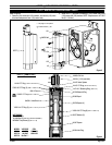
119380 Coil Nut
135
Figure 4
. 134
133
67277-( )
.Torque to 40 - 50 in. lbs (4.5 - 5.6 Nm).
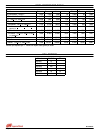
Z See page 4 for coil options.
~ Included in 67277-( ) Kit.
MODEL VOLTAGE COIL
67277-1 24 VDC 116218-39
67277-2 120 VAC 116218-33
67277-3 No Coil Z
43
101
116218-( ) Coil (see table)
114102 Valve System
114103 O" Ring (1.5 mm x 5.5 mm o.d.)
114104 O" Ring (1.5 mm x 14.5 mm o.d.)
Y147-16-C Retaining Ring (1.804" o.d.)
Y325-126 O" Ring (2) (3/32" x 1-9/16" o.d.)
94728 Solenoid Plug
92011 Piston
Y186-51 U" Cup (3/16" x 1-3/8" o.d.)
92005 Spool
92876 Spacer (4)
Y325-126 O" Ring (6) (3/32" x 1-9/16" o.d.)
Y325-214 O" Ring (5) (1/8" x 1-1/4" o.d.)
92877 Washer (5)
94027 Spacer
94032-1 Valve Block
94034 Inlet Plug
67277-( ) PARTS LIST
NOT SHOWN
CHW Connector
Y16-203 Ball (2) (3/32" dia, press flush w/94032-1)
96728647 Cap Screw (2) (M3 - .5 x 18)
Figure 3
~ 29670 Ball