


Page 4 of 4 6720X-XXX (en)
PN 97999-788
Assemble cup packings with lips facing away from each
other. Torque (30) nut to 50 ft lbs (67.8 Nm).
Assemble (31) cotter pin, securing (30) nut.
Slide (26) pump rod and (65) cup packings into (9) tube,
being careful not to damage the lips of cup packings.
NOTE: On models 6720X-F4X, thoroughly lubricate the
inside of (9) tube with a lubricant compatible with the
application, prior to assembly.
Assemble two (16) seals to each (17) downtube, assem-
bling with large i.d. onto downtube.
Assemble two (17) downtubes to (18) lower body.
Assemble (7) “O” ring and (9) tube to (18) lower body.
Screw three (12) nuts onto top end of (10) tie rods and
screw tie rods into (11) upper body.
Assemble (38) “O” ring into (11) upper body, securing
with (2) gland nut.
Assemble (43) wave spring, (53) male washer, five (51
and 52) “V” packings, (50) female packing washer, (44)
washer and (77) bushing into (11) upper body and screw
(1) solvent cup loosely into (11) upper body, securing
packings.
Assemble (7) “O” ring into (11) upper body and assemble
(11) upper body to (9) tube, aligning three (10) tie rods
with (18) lower body.
Assemble three (8) lock washers and three (12) tie rod
nuts to (10) tie rods, tightening to 60 ft lbs (81.4 Nm).
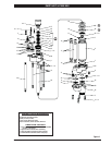
Turn pump assembly upside down and assemble two
(21) balls, two (35) “O” rings, (32 and 39) seats (chamfered
side into lower body rst) and two (20) “O” rings into (18)
lower body. Refer to gure 2, page 3, for the location of
(39) seat (with ori ce).
Assemble (34) inlet body to (18) lower body, secur-
ing with four (5) lock washers and four (4) bolts. NOTE:
Torque (4) bolts to 45 ft lbs (61.0 Nm).
Assemble (15) “O” rings to groove in (27) upper seats and
3.
4.
5.
6.
7.
8.
9.
10.
11.
12.
13.
14.
15
.
set upper seats on (11) upper body. Set (14) balls on (27)
upper seats. NOTE: Assemble upper seats with cham-
fered side up.
Assemble two (28) “O” rings to (6) ball cap and assemble
ball cap to (11) upper body, securing with four (5) lock
washers and four (4) bolts. NOTE: Torque (4) bolts to 45 ft
lbs (61.0 Nm).
Tighten (2) gland nut to 100 ft lbs (135.6 Nm).
TROUBLE SHOOTING
No material at outlet (pump continually cycles).
Check material supply, disconnect or shut o the air sup-
ply and replenish the material, reconnect.
Material on one stroke only (fast downstroke).
The (21) ball may not be seating in the (32) lower seat
(see lower pump disassembly). Remove the ball from the
lower seat, clean and inspect the ball and seat area. If ball
or lower seat is damaged, replace.
Material on one stroke only (fast upstroke).
The (21) ball may not be seating in the (39) lower seat (see
lower pump disassembly). Remove the ball from the low-
er seat, clean and inspect the ball and seat area. If ball or
lower seat is damaged, replace. Check for worn or dam-
aged seals. Replace the seals as necessary. Also, check for
a damaged ori ce in (39) seat.
Material leakage out of the solvent cup or material
appears on the pump plunger rod.
Tighten the solvent cup until leakage discontinues. If this
procedure does not aid in stopping the leakage problem,
the upper packings may be worn (see lower pump disas-
sembly). Replace the packings as necessary.
16.
17.
y
y
y
y