


67072Page4of4
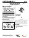
1” METALLIC DIAPHRAGM PUMP CONTROLLER INSTALLATION
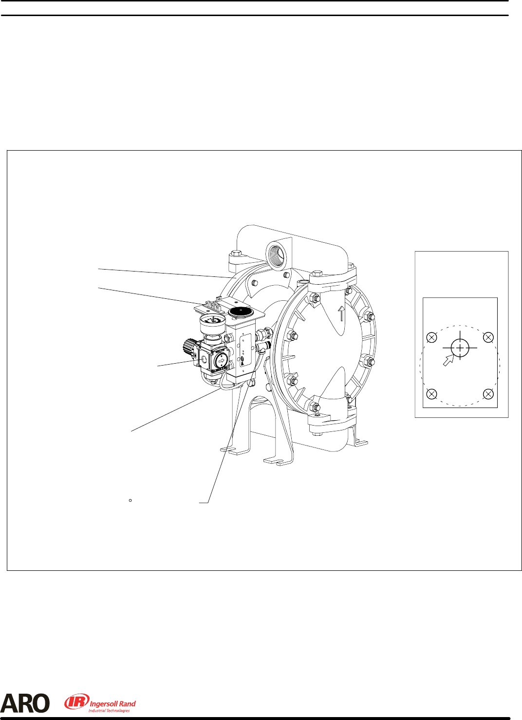
1” METALLIC DIAPHRAGM PUMPS ONLY (see figure 5)
NOTE: Refer to the pump Operator’s Manual.
1. On the air inlet side of the pump, remove the four Major Valve cap
screws, 92003 leg and 92878 gasket.
2. The leg of a 1” metallic diaphragm pump must be modified. Use the
93913 template included as a guide (drill a 1/2” hole).
3. Replace the old 92878 gasket with new 92878 gasket provided in
the kit.
4. Position the modified leg.
5. Place the 92004 gasket on the leg.
6. Install the 93911 adapter plate with the 1/8 - 27 N.P.T.F. - 1 tapered
threads outward, secure the plate with four screws and lockwash-
ers. NOTE: The elbow cannot be installed if the plate is reversed.
7. Remove the tubing from the 90_ elbow and assemble the 59756-4
90_ tubing elbow into the adapter plate.
8. Attachthekittothepump inletas shownandre -attach thetubeto the
59756-4 90_ elbow.
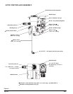
PN 97999-596
90 Tubing Elbow
Signal Tube
Figure 5
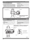
1" METALLIC DIAPHRAGM PUMP
REASSEMBLY ORDER
1. 92878 Gasket
2. 92003 Modified Leg (with new hole drilled by installer)
3. 92004 Gasket
4. 93911 Adapter Plate
5. Lockwasher (4)
6. Y6-45-C Screw (4)
(1/4" - 20 x 1")
Air Inlet
67072 Controller
1" Diaphragm Pump
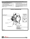
93913 TEMPLATE
FOR USE WITH
1" METALLIC LEG
ALIGN THE FOUR 9/32" DIA. TEMPLATE HOLES WITH THE
FOUR LEG BOLT HOLES.
ALINEE LOS CUATRO ORIFICIOS DE 9/32" DE DIÁMETRO
DE LA PLANTILLA CON LOS CUATRO ORIFICIOS DE LOS
PERNOS DE LAS CUATRO PATAS.
ALIGNER LES QUATRE TROUS DU GABARIT DE 9/32" DE
DIAMÈTRE AVEC LES QUATRE TROUS DE BOULON DE LA
PATTE.
DRILL A .500" DIA. HOLE THROUGH THE LEG HERE.
PERFORE AQUÍ UN ORIFICIO DE .500" DE DIÁMETRO A
TRAVÉS DE LA PATA.
PERCER ICI UN TROU DE 0,500" DE DIAMÈTRE DANS LA
PATTE.
P/N 93913