


66M150-XXX-C (en) Page 3 of 8
y
Viton®and Hytrel® are registered trademarks of the DuPont Company
y
Loctite® is a registered trademark of Henkel Loctite Corporation
y
y
Santoprene® is a registered trademark of Monsanto Company, licensed to Advanced Elastomer Systems, L.P.
y
ARO® is a registered trademark of Ingersoll-Rand Company
y
y
262™, 271™ and 572™ are trademarks of the DuPont Company
y
MAINTENANCE
Refer to the part views and descriptions as provided on
pages 4 through 7 for parts identi cation and service kit in-
formation.
Certain ARO “Smart Parts” are indicated which should be
available for fast repair and reduction of down time.
Service kits are available to service two separate
diaphragm pump functions: 1. AIR SECTION, 2. FLUID
SECTION. The Fluid Section is divided further to match
typical part Material Options.
Provide a clean work surface to protect sensitive internal
moving parts from contamination from dirt and foreign
matter during service disassembly and reassembly.
Keep good records of service activity and include the
pump in preventive maintenance program.
Before disassembling, empty captured material in the
outlet manifold by turning the pump upside down to
drain material from the pump.
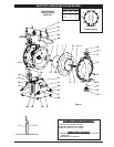
FLUID SECTION DISASSEMBLY
Remove top manifold(s).
Remove (22) balls, (19) “O” rings and (21) seats.
Remove (15) uid caps.
Remove (14) screws, (6) washers, (7) diaphragms and (5)
washers.
Remove (3) “O” rings.
NOTE: Do not scratch or mar the surface of (1) diaphragm
rod.
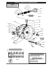
FLUID SECTION REASSEMBLY
Reassemble in reverse order.
Clean and inspect all parts. Replace worn or damaged
parts with new parts as required.
Lubricate (1) diaphragm rod and (2) “O” ring with Key-
Lube “O” ring lube.
Use ARO pn 98931-T bullet (installation tool) to aid in in-
stallation of (2) “O” ring on (1) diaphragm rod.
Be certain (7) diaphragms align properly with (15) fluid
caps before making nal torque adjustments on bolt and
nuts to avoid twisting the diaphragm.
Re-check torque settings after pump has been re-started
and run a while.
y
y
y
y
y
1.
2.
3.
4.
5.
y
y
y
y
y
y
WARNING
= Hazards or unsafe practices which
could result in severe personal injury,
death or substantial property damage.
CAUTION
= Hazards or unsafe practices which
could result in minor personal injury,
product or property damage.
NOTICE
= Important installation, operation or
maintenance information.
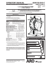
GENERAL DESCRIPTION
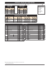
The ARO diaphragm pump o ers high volume delivery even
at low air pressure and a broad range of material compatibil-
ity options are available. Refer to the model and option chart.
ARO pumps feature stall resistant design, modular air motor
/ uid sections.
Air operated double diaphragm pumps utilize a pressure dif-
ferential in the air chambers to alternately create suction and
a positive uid pressure in the uid chambers, valve checks
insure a positive ow of uid.
Pump cycling will begin as air pressure is applied and it will
continue to pump and keep up with the demand. It will build
and maintain line pressure and will stop cycling once maxi-
mum line pressure is reached (dispensing device closed) and
will resume pumping as needed.
AIR AND LUBE REQUIREMENTS
WARNING
EXCESSIVE AIR PRESSURE. Can cause pump
damage, personal injury or property damage.
A filter capable of filtering out particles larger than 50
microns should be used on the air supply. There is no lu-
brication required other than the “O” ring lubricant which
is applied during assembly or repair.
If lubricated air is present, make sure that it is compatible
with the “O” rings and seals in the air motor section of the
pump.
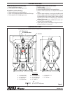
OPERATING INSTRUCTIONS
Always flush the pump with a solvent compatible with
the material being pumped if the material being pumped
is subject to “setting up” when not in use for a period of
time.
Disconnect the air supply from the pump if it is to be in-
active for a few hours.
The outlet material volume is governed not only by the
air supply, but also by the material supply available at the
inlet. The material supply tubing should not be too small
or restrictive. Be sure not to use hose which might col-
lapse.
When the diaphragm pump is used in a forced-feed
( ooded inlet) situation, it is recommended that a “check
valve” be installed at the air inlet.
Secure the diaphragm pump legs to a suitable surface to
insure against damage by vibration.
y
y
y
y
y
y
y