


6662AX-X-C Page 3 of 8
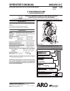
GENERAL DESCRIPTION
The ARO diaphragm pump offers high volume delivery even
at low air pressure and a broad range of material compatibility
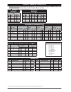
options available. Refer to the model and option chart. ARO
pumps feature stall resistant design, modular air motor / uid
sections.
Air operated double diaphragm pumps utilize a pressure dif-
ferential in the air chambers to alternately create suction and
positive uid pressure in the uid chambers, ball checks insure
a positive ow of uid.
Pump cycling will begin as air pressure is applied and it will
continue to pump and keep up with the demand. It will build
and maintain line pressure and will stop cycling once maxi-
mum line pressure is reached (dispensing device closed) and
will resume pumping as needed.
AIR AND LUBE REQUIREMENTS
WARNING
EXCESSIVE AIR PRESSURE. Can cause pump
damage, personal injury or property damage.
A filter capable of filtering out particles larger than 50
microns should be used on the air supply.
There is no lu-
brication required other than the “O” ring lubricant which is
applied during assembly or repair.
When lubricated air is necessary, supply the air lubricator
with a good grade of SAE 90 wt. non-detergent oil and
set the lubricator to a rate not to exceed one drop per
minute.
y
y
OPERATING INSTRUCTIONS
Always ush the pump with a solvent compatible with the
material being pumped if the material being pumped is
subject to setting up” when not in use for a period of time.
Disconnect the air supply from the pump if it is to be inactive
for a few hours.
The outlet material volume is governed not only by the air
supply but also by the material supply available at the inlet.
The material supply tubing should not be too small or restric-
tive. Be sure not to use hose which might collapse.
When the diaphragm pump is used in a forced-feed ( ooded
inlet) situation, it is recommended that a “Check Valve” be
installed at the air inlet.
Secure the diaphragm pump legs to a suitable surface to in-
sure against damage by vibration.
y
y
y
y
y
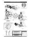
MAINTENANCE
Refer to the part views and descriptions as provided on page 4
through 7 for parts identi cation and Service Kit information.
Certain ARO “Smart Parts” are indicated which should be
available for fast repair and reduction of down time.
Service kits are divided to service two separate dia-
phragm pump functions: 1. AIR SECTION, 2. FLUID SEC-
TION. The FLUID SECTION is divided further to match
typical part MATERIAL OPTIONS.
Provide a clean work surface to protect sensitive internal
moving parts from contamination from dirt and foreign
matter during service disassembly and reassembly.
Keep good records of service activity and include pump
in preventive maintenance program.
Before disassembling empty captured material in the
outlet manifold by turning the pump upside down to
drain material from the pump.
y
y
y
y
y
Viton
®
and Hytrel
®
are registered trademarks of the DuPont
®
Company. Keynar
®
is a registered trademark of Penwell Corp
Santoprene
®
is a registered trademark of Monsanto Company, licensed to Advanced Elastomer Systems, L.P. Key-Lube
®
is a registered trademark of Key Industries
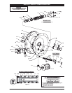
FLUID SECTION DISASSEMBLY
Remove top manifold(s).
Remove (22) balls, (19 and 33) “O” rings and (21) seats.
Remove (15) uid caps.
NOTE: Only PTFE diaphragm models use a primary dia-
phragm (7) and a backup diaphragm (8). Refer to the auxil-
iary view in the Fluid Section illustration.
4.
Remove the (6) nut, (7) or (7 / 8) diaphragms and (5) washers.
5. Remove (3 and 4) “O” rings.
NOTE: Do not scratch or mar the surface of (1) diaphragm rod.
1.
2.
3
.
FLUID SECTION REASSEMBLY
Reassemble in reverse order.
Clean and inspect all parts. Replace worn or damaged
parts with new parts as required.
Lubricate (1) diaphragm rod and (2) “O” ring with
KeyLube® grease.
Use ARO PN / 98931-T Bullet (installation tool) to aid in
installation of (2) “O” ring on (1) diaphragm rod.
Be certain (7) or (7 / 8) diaphragm(s) align properly with
(15) uid caps before making nal torque adjustments on
bolt and nuts to avoid twisting the diaphragm.
For models with PTFE diaphragms: Item (8) Santoprene
diaphragm is installed with the side marked “AIR SIDE” to-
wards the pump center body. Install the PTFE Diaphragm
with the side marked “FLUID SIDE” towards the uid cap.
Recheck torque settings after pump has been restarted
and run awhile.
y
y
y
y
y
y
y