


6661HX-XXX-C (en) Page 3 of 8
y
Loctite® is a registered trademark of Henkel Loctite Corporation
y
271™, 262™, 572™ and 577™ are trademarks of Henkel Loctite Corporation
y
y
Hytrel® and Viton® are registered trademarks of the DuPont Company
y
ARO® is a registered trademark of Ingersoll-Rand Company
y
MAINTENANCE
Certain ARO “Smart Parts” are indicated which should be
available for fast repair and reduction of down time.
Provide a clean work surface to protect sensitive internal
moving parts from contamination from dirt and foreign
matter during service disassembly and reassembly.
Keep good records of service activity and include the
pump in preventive maintenance program.
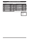
Service kits are available to service two separate dia-
phragm pump functions: 1. GAS SECTION, 2. FLUID SEC-
TION. The Fluid Section is divided further to match typical
active Material Options.
Before disassembling, empty captured material in the
outlet manifold by turning the pump upside down to
drain material from the pump.
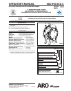
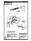
FLUID SECTION DISASSEMBLY
Remove top manifold(s).
Remove (22) balls, (19) “O” rings and (21) seats.
Remove (15) uid caps.
Remove (14) screws, (6) washers, (7) diaphragms and (5)
washers.
Remove (3) “O” rings. NOTE: Do not scratch or mar the
surface of (1) diaphragm rod.
FLUID SECTION REASSEMBLY
Reassemble in reverse order.
Clean and inspect all parts. Replace worn or damaged
parts with new parts as required.
Lubricate (1) diaphragm rod and (2) “O” ring with Key-
Lube grease.
Use ARO pn 98930-T bullet (installation tool) to aid in in-
stallation of (2) “O” ring on (1) diaphragm rod.
Be certain (7) diaphragms align properly with (15) fluid
caps before making nal torque adjustments on bolt and
nuts to avoid twisting the diaphragm.
Re-check torque settings after pump has been re-started
and run a while.
y
y
y
y
y
1.
2.
3.
4.
5.
y
y
y
y
y
y
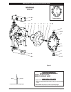
GENERAL DESCRIPTION
The ARO natural gas powered diaphragm pump o ers high
volume delivery even at low gas pressure. Natural gas pow-
ered diaphragm pumps move fluids such as crude oil, salt
water, drilling mud, lubrication oils, glycol, caustic liquids and
acids. ARO pumps feature stall resistant design, modular gas
motor / uid sections.
Gas operated double diaphragm pumps utilize a pressure
differential in the gas chambers to alternately create suc-
tion and a positive uid pressure in the uid chambers, ball
checks insure a positive ow of uid.
Pump cycling will begin as gas pressure is applied and it will
continue to pump and keep up with the demand. It will build
and maintain line pressure and will stop cycling once maxi-
mum line pressure is reached (dispensing device closed) and
will resume pumping as needed.
GAS AND LUBE REQUIREMENTS
WARNING
EXCESSIVE GAS PRESSURE. Can cause pump
damage, personal injury or property damage.
A filter capable of filtering out particles larger than 50
microns should be used on the gas supply. There is no lu-
brication required other than the “O” ring lubricant which
is applied during assembly or repair.
If lubricated gas is present, make sure that it is compat-
ible with the “O” rings and seals in the gas motor section
of the pump.
OPERATING INSTRUCTIONS
Always flush the pump with a solvent compatible with
the material being pumped if the material being pumped
is subject to “setting up” when not in use for a period of
time.
Disconnect the gas supply from the pump if it is to be
inactive for a few hours.
The outlet material volume is governed not only by the
gas supply, but also by the material supply available at
the inlet. The material supply tubing should not be too
small or restrictive. Be sure not to use hose which might
collapse.
When the diaphragm pump is used in a forced-feed
( ooded inlet) situation, it is recommended that a “check
valve” be installed at the gas inlet.
Secure the diaphragm pump legs to a suitable surface to
insure against damage by vibration.
y
y
y
y
y
y
y