


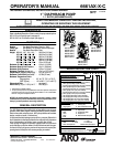
PAGE 3OF86661AX-X-C
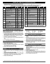
AIR AND LUBE REQUIREMENTS
WARNING
EXCESSIVE AIR PRESSURE. Can cause pump
damage, personal injury or property damage.
S Afiltercapableoffilteringoutparticleslargerthan50micronsshould
beusedonthe airsupply.Thereisnolubrication requiredotherthan
the “O” ring lubricant which is applied during assembly or repair.
S If lubricatedair is present,make sure thatis compatiblewith the Ni-
trile “O” rings in the air motor section of the pump.
OPERATING INSTRUCTIONS
S
Always flush the pump with a solvent compatible with the material
beingpumpedifthematerialbeing pumpedissubjectto ‘‘settingup”
when not in use for a period of time.
S Disconnecttheairsupplyfromthepumpifitistobeinactiveforafew
hours.
S Theoutletmaterialvolume isgoverned notonly bytheair supplybut
alsobythematerialsupplyavailableattheinlet.Thematerialsupply
tubingshould notbetoo smallorrestrictive. Besurenotto usehose
which might collapse.
S When the diaphragm pump is used in a forced-feed (flooded inlet)
situation it isrecommended that a “Check Valve” be installed atthe
air inlet.
S Secure the diaphragm pump legs to a suitable surface to insure
against damage by vibration.
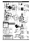
MAINTENANCE
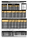
Refertothepartviewsanddescriptionsasprovidedonpage4through7
for parts identification and Service Kit information.
S Certain ARO“Smart Parts” areindicated whichshould beavailable
for fast repair and reduction of down time.
S Service kits are divided to service two separate diaphragm pump
functions: 1.AIR SECTION, 2.FLUID SECTION. The FLUIDSEC-
TION isdivided further tomatch typical partMATERIAL OPTIONS.
S Provide a clean work surface to protect sensitive internal moving
partsfrom contaminationfrom dirtandforeignmatterduring service
disassembly and reassembly.
MAINTENANCE CONTINUED
S
Keep good records of service activity and include pump in preven-
tive maintenance program.
S Beforedisassemblingemptycapturedmaterialintheoutletmanifold
by turning the pump upside down to drain material from the pump.
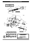
FLUID SECTION DISASSEMBLY
1. Remove top manifold(s).
2. Remove (22) balls, (19 and 33) “O” rings and (21) seats.
3. Remove (15) fluid caps.
NOTE: OnlyPTFEdiaphragm modelsusea (7)primary diaphragmand
an(8) backupdiaphragm.Referto theauxiliary viewintheFluidSection
illustration.
4. Remove the (6) nut, (7) or (7 / 8) diaphragms and (5) washers.
5. Remove (3 and 4) “O” rings.
NOTE: Do not scratch or mar the surface of (1) diaphragm rod.
FLUID SECTION REASSEMBLY
S
Reassemble in reverse order.
S Clean and inspect all parts. Replace worn or damaged parts with
new parts as required.
S Lubricate (1) diaphragm rod and (2) “O” ring with Key-LubeR
grease.
S Use ARO PN/ 98930-T Bullet (installation tool) toaid in installation
of (2) “O” ring on (1) diaphragm rod.
S Be certain (7) or (7 / 8) diaphragm(s) align properly with (15) fluid
caps before making final torque adjustments on bolt and nuts to
avoid twisting the diaphragm.
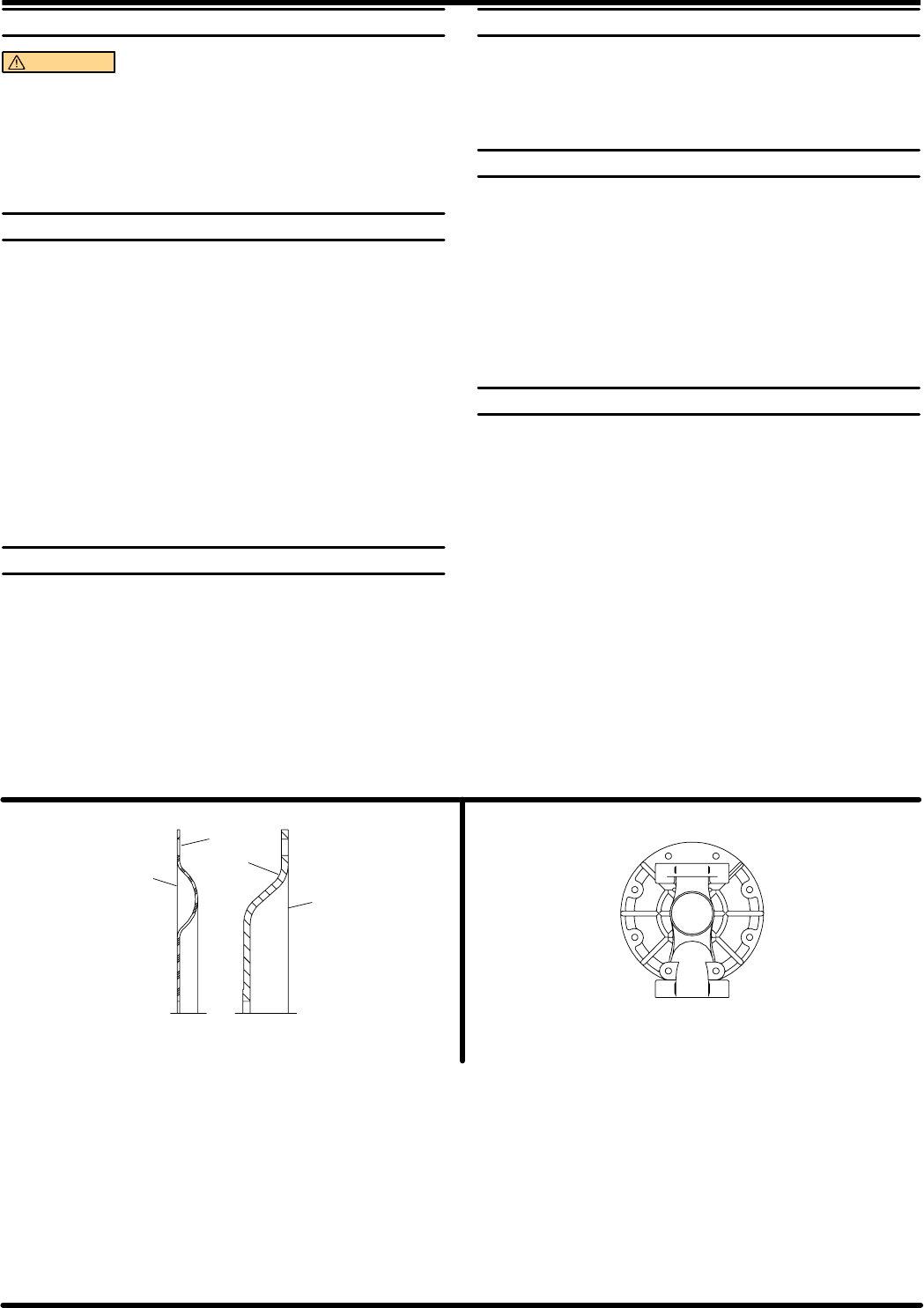
S FormodelswithPTFEdiaphragms:Item(8)Santoprenediaphragm
is installedwith theside marked“AIR SIDE”towardsthe pumpcen-
ter body. Install the PTFE Diaphragm with the side marked “FLUID
SIDE” towards the fluid cap.
S Re-check torque settingsafter pump hasbeen re-startedand run a
while.
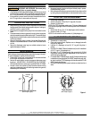
Air
Side
Fluid Side
Fluid
Side
AirSide
CROSS SECTIONVIEWOF DIAPHRAGMS
(Referto figure3, page5)
8
1
6
4
3
5
7
2
Torque Sequence
(Referto figure3, page5)
Figure 2
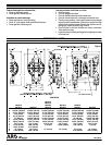
SVitonRandHytrelRaretrademarksoftheDuPontCompanySKynarRisatrademarkofPenwaltCorp.
SSantoprene
RisatrademarkoftheMonsantoCompany,licensedtoAdvancedElastomerSystems.L.P. SKey-LubeRisaregisteredtrademarkofKeyIndustries