


Page 2 of 4 66260X
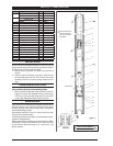
Item Description
(size in inches)
Qty Part No.
1 Tube
(662605 & 662606)
(1) 92625-1
(662608 & 662609)
(1) 92625-2
2 Rod
(662605 & 662606)
(1) 92629-1
(662608 & 662609)
(1) 92629-2
3 Adapter (1) 92621
4 Pin (1) 92624
5 BaIl Guide (1) 92623
6 BalI (1) Y16-211
7 Piston and CyIinder (1) 66714
8 Gasket (1) 92628
9 Tube (1) 92627
10 Primer Rod (1) 90131
11 Washer (1) 90136
12 Foot Valve Sleeve (1) 4170
13 Snap Ring (1) Y147-77
14 Cup (1) 90757
15 Body (1) 90756
16 Washer (1) F21-56
17 Foot Valve Seat (1) 93269-1
18 Washer (1) 90133
19 Washer (1) 92630
20 Elastic Stop Nut (1) 95977302
21 Primer Tube (1) 92626
PARTS LIST / LOWER PUMP END
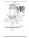
INSTALLATION
Remove pump from packaging material and install and secure
pump to cover, bung or other mounting accessory as ordered.
See gure 2 for view of complete assembly.
Before connecting pump, first blow out material line
with air.
After the system is hooked up, pump a small amount
of material through the line. This material should be
discarded. (Do this to clear any foreign material out of
lines).
1.
2
.
OPERATING INSTRUCTIONS
Be sure material hose, lines and other components are
able to withstand pressure developed by pumps.
When a pump is installed and ready to operate: Connect air
supply to air motor inlet. Regulate air pressure from p.s.i.g
(2.07 bar) to 50 p.s.i.g (3.4 bar). Allow pump to cycle slowly
to prime with material and bleed all air from system
.
1.
MAINTENANCE
If the pump is to be inoperative for a lengthly period of time (a
few hours), disconnect air and relieve all pressure from system.
Periodically flush pump with a solvent that is compatible
with material being pumped.
Disassembly should be done on a clean work bench with
clean cloths to keep parts clean.
If replacement parts are necessary, consult drawings contain-
ing parts for identi cation.
Before reassembling, lubricate parts where required. When
assembling “0” rings or parts adjacent to “0” rings, care must
be exercised to prevent damage to “0” rings and “0” ring
groove surfaces.
Clean threads with
solvent and apply
Loctite 271 sealant
to threads.
See View “A”
1
2
3
4
5
6
7
8
9
10
11
12
16
18
19
20
21
15
17
13
14
View “A”
Figure 2
(1 & 9) 300 ft lbs (406.8 Nm) minimum.
TORQUE REQUIREMENTS