


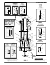
LOWER PUMP DISASSEMBLY
LOWER PUMP REASSEMBLY
PAGE 4 OF 4
66243-X
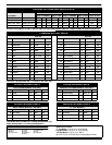
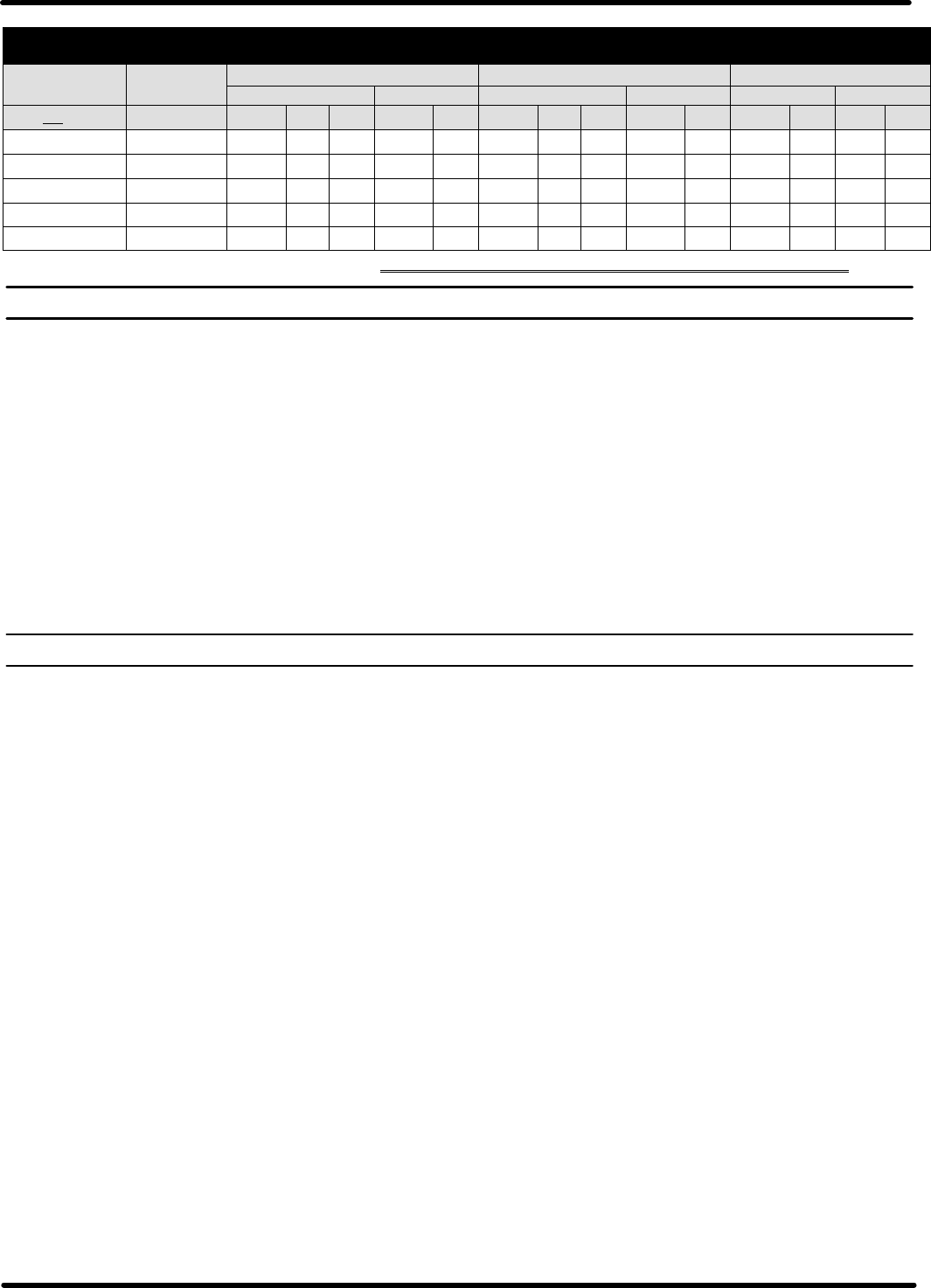
PACKING OPTIONS AND SERVICE KITS
LOWER SERVICE UPPER PACKING MIDDLE PACKING LOWER PACKING
PUMP KIT
51 (X) ‘‘V” PACKING 52 (2) ‘‘V PKG
55 (X) ‘‘V” PKG
56 (2) ‘‘V” PKG
59 (4) ‘‘V” PKG
65 (1)‘‘U”
CUP
66243-XXX 637071-XXX PART # (QTY) [MT’L] PART # [MT’L] PART# (QTY) [MT’L] PART # [MT’L] PART # [MT’L] PART# [MT’L]
-11X -, -15X -
637071-G43,-G47
93454-1 (5) [L] 93455-1 (4) [L] 93678-1 [L]
-31X -,-343,-35X-
637071-G43,-G47
93454-2 (5) [T]
93455-2
(4) [T] 90911 [T]
-51X -,-55X-
637071-G43,-G47
93454-2 (3) [T] 93454-1 [L] 93455-2 (4) [T] 90911 [T]
-C1X-,- C4X,- C5X-
637071-C43,-C47
93454-4 (5) [UH] 93455-4 (4) [UH] 90911 [T]
-D1X-,- D5X-
637071-G43,-G47
93454-4 (3) [UH] 93454-1 [L] 93455-1 (4) [L] 93678-1 [L]
- As ofMay 15, 1995 these models are no longer available. EXAMPLE: 66243-117 is replaced by 66243-G47 & service kit is 637071-G47.
Note: All threads are right hand.
1. Remove(6) pump body from (9) suction tube, by sliding it off three
(10) tie rods.
2. Remove (7) gasket from top of (9) suction tube.
3. Remove three (10) tie rods.
4. Pull(9) suction tube off the MIDDLE packing andvalve section and
out of (25) adapter.
5. Push (26) plunger rod to expose the primer assembly.
6. Remove(33)nut, (32) valveplate and (31) washerfrom (30) primer
rod.
7. Pull (26) plunger rod and remove MIDDLE packing, valve section
and (30) rod from (15) chamber body.
8. Remove (7) gasket out of (25) adapter.
9. Withthe aid of a flat bladed screwdriver remove (25) adapter, (21)
valve body,(22) valve seat and two (23) gaskets out of (15) cham-
ber body. Use the flat bladed screwdriver to pry on the slot on (25)
adapter.
10. Remove (24) ‘‘O” Ring from (25) adapter.
11. Withretaining ring pliers,remove (37)retaining ring from (21) valve
body, then remove the packings out of (21) valve body.
12. Using provided wrench flats, remove (30) rod from (34) valve rod.
Again, using wrench flats remove (34) valve rod from (26) plunger
rod.
CAUTION: DO NOT mar or damage surfaces of any of these rods.
13. Slide the MIDDLE packing assembly off (34) valve rod.
14. Clamp(34) valveseatina viseandremove (36)valveseat nut,then
remove the MIDDLE packing assembly off (28) valve seat.
15. Remove (1) solvent cupfrom (6) pump body. Now remove UPPER
packing assembly out (6) pump body.
Note: All rubber goods and packings should be lubricated with a com-
patible lubricant prior to assembly.
1. Assemble(21) valve bodywith LOWER packings.Referto Packing
Options Chart on page 2.
2. RetainLOWER packing assy. in (21) valve body with (37)retaining
ring.
3. Assemble(28) valve seat MIDDLEpackings. Refer toPacking Op-
tions Chart on page 2.
4. Secure the MIDDLE packing assy. with (36) valve seat nut.
5. Slide(21)valvebodywithLOWERpackingsontotheendof(30)rod
opposite the wrench flats. Install (21) valve body with the beveled
end onto rod
6. Screw (30) rod into (34) valve body and tighten.
7. Place (24) ‘‘O” Ring on (25) adapter.
8. Slide(25) adapter onto the (34) valvebody & (30) rod assy with the
wider diameter opening going on first & fit it over (21) body.
9. Slide (28) valve seat and MIDDLE packing assy over (34) valve
body.Be sure to place beveled endof (28) valveseat against bevel
of (34) valve body.
10. Screw (34) valve body into (26) plunger rod and tighten. Use
wrench flats.
11. Placeone (23) gasketinside (15) chamber body, followed with (22)
valve seat with beveled side up. NOTE: If stringy or filled materi
alisbeingpumped,then reversethe(22)valveseat.Nextplace
second (23) brass gasket against t op of (22) valve seat.
12. Place(26)plunger,(28)valveseatandMIDDLEpackingassyalong
with (30) rod & (25) adapter assy into (15) chamber body with the
primer rod end going in first.Slidethe (25) adapter into place in the
(15) chamber body.
13. Place (7) gasket in (25) adapter.
14. Lubricate the MIDDLE packing assy and the inside of (9) suction
tube.Carefully slide(9) suctiontubeover (26)plunger andMIDDLE
packing assy into (15) adapter.
15. Install three (10) tie rods.
16. Place (7) gasket on end of (9) suction tube. NOTE: Apply a small
amount of grease on gasket to help keep gasket in place.
17. Slide (6) pump body over (26) plunger rod onto (10) tie rods. Seat
the (9) suction tube into (6) pump body.
18. Assemble the UPPER packing onto the (26) plunger rod and slide
into (6) pump body.
19. Install (1) solvent cup and hand tighten.
20. Push (26) plunger rod to expose (30) rod at bottomof pump. Place
(31) washer, (32) plate with beveled edges away from pump and
(33) nut onto (30) rod. Tighten (33) nut.
21. Push (30) rod untilrod is inside (15) chamberbody. Tighten (1) sol-
vent cup.
PN 97999-070