


OPERATOR’S MANUAL
66243--X
RELEASED: 7--7--90
REVISED: 6--4--10
(REV. F) IPP
INCLUDING: SERVICE KIT, TROUBLESHOOTING, PARTS LIST,
DISASSEMBLY AND ASSEMBLY
IMPORTANT: READ THIS MANUAL CAREFULLY BEFORE INSTALLING,
OPERATING OR SERVICING THIS EQUIPMENT.
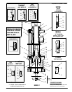
CHOP--CHECK STYLE
LOWER PUMP END
ALSO COVERS 637071-XXX SERVICE KIT
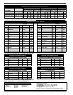
1 COIL SPRING.-
4 WAVE SPRING
5 C OMPOSITE SPRING W/ADJ P’KGNUT -
- AS OF MAY 15, 1995 NO LONGER AVAILABLE
D
UHMW--PE/LEATHER STAG’D(UPPER)
LEATHER (LOWER)
-
5
PTFE(GF)/LEATHER STAG’D (UPPER)
GLASS FILLED PTFE (LOWER)
-
1 T HIOKOL LEATHER -
P
UHMW--PE/PTFE STAG’D (UPPER)
UHMW--PE (LOWER)
R PTFE/UHMW--PE STAG’D(UPPER)
PTFE (LOWER)
(PACKINGSARE UPPERAND LOWERUNLESSNOTED)
LOWER PUMP END OPTION
DESCRIPTION CHART*
66243--XXX
PACKING MATERIAL
3 GLASS FILLED PTFE
PACKING MATERIAL
_____
PLUNGER TYPE
SPRING ARRANGEMENT
SPRING ARRANGEMENT
PLUNGER TYPE
3 H D SS W/HD CHROME PLATING
*NOTALL MODELCOMBINATIONSAREAVAILABLE,REFERTOPUMPMODEL MANUAL(650XXX--XXX)FOR‘‘ACTIVE”MODELS.
C UHMW--PE
G UHMW--PE/LEATHER STAG’D
7 THREADED PLUNGER (LG MOTORS)
SERVICE KITS
• Use only genuine ARO replacement parts to assure compatible-
pressure rating and longest service life.
• 637071--XXX for general repair of 66243--XXX Lower Pump End.
GENERAL DESCRIPTION
LOWER PUMP END
WARNING
DONOT EXCEEDMAXIMUM OPERATINGPRES-
SURE AS INDICATED ON PUMP MODEL PLATE
WARNING
REFER TO GENERAL INFORMATION SHEET
FOR ADDITIONAL SAFETY PRECAUTlONS AND IMPORTANT
INFORMATION.(See thepump model manual for the proper Form
No.)
• ThisLOWERPUMPEND MANUALisoneof fourdocumentsneed-
ed to properly supportan ARO pump model.Ref: Part A. 650XXX--
XXX--X MODEL (OPERATOR’S) MANUAL, Part B. GENERAL
INFORMATION, Part C. MOTOR (OPERATOR’S) MANUAL, Part
D. LOWER PUMP END (OPERATOR’S) MANUAL. These forms
are available from the factory if needed.
• TheChop--Check designprovides fareasypriming ofthe lowerfoot
valve. The double acting feature is standard in all ARO industrial
pumps, material is delivered to the pump discharge outlet on both
the up and down stroke.
PUMP RATI0 X REGULATED = MAXIMUM FLUID PRESSURE
PRESSURE
• The pump ratio is an expression ofthe relationshipbetween theair
motor area and the lower pump end area. EXAMPLE: When 150
PSI (10.3 Bar) air pressure is supplied to the pump motor on a 3:1
ratio pump,the lower pump end willdevelop a maximum of450 PSI
(31Bar)fluidpressure(atnoflow).Asthefluidcontrolisopened,the
flow rate will increase as the motor cycle rate increases to keep up
with the demand.
• Operating at excessive pressures will shorten the life of the pump.
TROUBLE SHOOTING CHOP- CHECK PUMPS
Lower Pump End Problems
• No material at outlet. (Pump continually cycles.)
Check material supply, disconnect or shut off the air supply and re-
plenish the material, reconnect.
• Material on one stroke only. (fast downstroke.)
The lower check may not be seating in the foot valve. (See lower
pump disassembly) Remove the check from the foot valve, clean
andinspect the valveseat area.If check orfoot valveare damaged,
replace.
• Material on one stroke only. (fast upstroke.)
• Checkfor wornor damagedseals. Replace theseals asnecessary.
• Material leakage out of the solvent cup or material appears on the
pump plunger rod.
ForModels(--X5XOnly).Increase theloadonthepackingsbytight-
ening the packing nut.
Check for worn upper packings and replace them as necessary.
INGERSOLL RAND COMPANY LTD
209 NORTH MAIN STREET – BRYAN, OHIO 43506
(800) 495-0276 FAX(800) 892-6276
© 2010
www.ingersollrandproducts.com