


Page 2 of 4 662420-B (en)
PARTS LIST
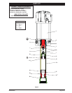
Item Description
(size)
Qty Part No. Mtl
1 Air Motor (1) 65441-B
2 Spacer (1) 96624 [Br]
3 Seal (1) 96625 [U]
5 Spring (1) 90120 [C]
6 Washer (1) 90125 [Co]
7 “O” Ring
(1/16” x 2-1/8” o.d.)
(1) Y325-33 [B]
8 Nut
(1/2” - 20)
(2) Y11-108-C [C]
9 Piston Rod (1) 76507 [C]
10 Cup Follower (1) 75678 [C]
11 Ball
(1.0000” diameter)
(1) Y16-232 [C]
12 Cup (1) 92867-1 [UH]
13 Washer (1) 75682 [C]
14 Inner Check Seat (1) 75681 [C]
Item Description
(size)
Qty Part No. Mtl
15 Tube (1) 76506 [C]
16 Ball Stop Pin
(3/16” o.d. x 1-13/16”)
(1) 83009 [C]
17 “O” Ring
(1/8” x 1-7/8” o.d.)
(1) Y325-223 [B]
18 Ball
(1.2500” diameter)
(1) Y16-240 [C]
19 Foot Valve Seat (1) 77006 [C]
20 Reducer
(1-1/2 11-1/2 NPT x 2 - 11-1/2 NPT)
(1) Y202-12 [I]
Lower Pump Assembly
(includes items
7 - 20)
(1) 60873
Items included in repair kit (1) 61053
Items included in packing kit (1) 65823
OPERATING AND SAFETY PRECAUTIONS
WARNING
HAZARDOUS PRESSURE. Do not exceed maxi-
mum operating pressure of 1350 p.s.i. (93.1 bar) at 150 p.s.i.
(10.3 bar) inlet air pressure.
Pump Ratio X = Maximum Pump
Inlet Pressure to Pump Motor Fluid Pressure
Pump ratio is an expression of the relationship between the pump motor area
and the lower pump end area. EXAMPLE: When 150 p.s.i. (10.3 bar) inlet pressure
is supplied to the motor of a 4:1 ratio pump, it will develop a maximum of 600 p.s.i.
(41.4 bar) uid pressure (at no ow) - as the uid control is opened, the ow rate
will increase as the motor cycle rate increases to keep up with the demand.
WARNING
Refer to general information sheet for additional
safety precautions and important information.
The two-ball pumps are primarily designed for the pumping of
medium viscosity fluids. The two-ball design provides better
priming of the lower foot valve. The double acting feature is
standard in all ARO industrial pumps. Material is delivered to
the pump discharge outlet on both the up and down stroke.
NOTICE: Thermal expansion can occur when the uid in the mate-
rial lines is exposed to elevated temperatures. Example: Material
lines located in a non-insulated roof area can warm due to sunlight.
Install a pressure relief valve in the pumping system.
Replacement warning label (pn 92325) is available upon re-
quest.
LOWER PUMP END DISASSEMBLY
NOTE: All threads are right hand.
While holding pump securely with a strap wrench, unthread
and remove (15) tube.
Loosen (8) nut against motor rod and unthread (9) piston rod
from motor rod.
Unthread and remove (14) inner check seat, releasing (13)
washer, (12) cup and (11) ball.
Loosen (8) nut to unthread and remove (10) cup follower from
(9) piston rod.
While holding (15) tube securely, unthread and remove (19)
foot valve seat and components.
Remove (16) ball stop pin, releasing (18) ball.
LOWER PUMP END ASSEMBLY
NOTE: Thoroughly clean and lubricate all seals. Replace all soft
parts with new ones included in the repair kit. Note: Refer to the
illustration ( gure 2, page 3) for packing lip direction.
Assemble (17) “O” ring, (18) ball and (16) ball stop pin to (19)
1.
2.
3.
4.
5.
6.
1.
foot valve seat.
Assemble (19) foot valve seat and components to (15) tube.
NOTE: Tighten (19) foot valve seat to 125 - 150 ft lbs (169.5 -
203.4 Nm).
Assemble (9) piston rod and (8) nut to (10) cup follower. NOTE:
Apply Loctite 242 to threads of (9) piston rod before assembly.
NOTE: Tighten (8) nut to 50 - 60 ft lbs (67.8 - 81.3 Nm).
Assemble (12) cup, (13) washer and (11) ball to (10) cup fol-
lower, securing with (14) inner check seat. NOTE: Tighten (14)
inner check seat to 65 - 70 ft lbs (88.1 - 94.9 Nm).
Assemble (3) seal, (2) spacer, (5) spring and (6) washer into cav-
ity in bottom of motor. NOTE: Refer to gure 2, page 3 for pack-
ing lip direction.
Assemble (8) nut and (9) piston rod and components to motor
rod, tightening (8) nut against motor rod. NOTE: Apply Loctite
242 to threads of (9) piston rod before assembly. NOTE: Tighten
(8) nut to 60 - 70 ft lbs (81.3 - 94.9 Nm).
Assemble (7) “O” ring to (15) tube and assemble (15) tube over
(10) cup follower and components and into air motor base.
NOTE: Tighten (15) tube to 90 - 100 ft lbs (122.0 - 135.6 Nm).
TROUBLE SHOOTING
Pump problems can occur in either the air motor section or the
lower pump end section. Use these basic guidelines to help deter-
mine which section is a ected.
Pump will not cycle.
Be certain to first check for non-pump problems including
kinked, restrictive or plugged inlet / outlet hose or dispensing
device. Depressurize the pump system and clean out any ob-
structions in the inlet / outlet material lines.
Refer to the motor manual for trouble shooting if the pump
does not cycle and / or air leaks from the air motor.
Inadequate air supply. Increase air pressure to the pump.
Obstructed material line. Remove obstruction.
Damaged motor. Service the motor.
Material on one stroke only (fast downstroke).
Ball (18) is not seating. Remove the ball from the foot valve,
clean and inspect the ball and foot valve seat area. If the ball or
foot valve is damaged, replace.
Material on one stroke only (fast upstroke).
Cup (12) is worn. Replace.
2.
3.
4.
5.
6.
7.
Loctite® and 242® are registered trademarks of Henkel Loctite Corporation
ARO® is a registered trademark of Ingersoll-Rand