


Page 2 of 2 65814-X-C (en)
PN 97999-1464
GENERAL DESCRIPTION
The two-ball pump design provides for easy priming of the lower
foot valve. The double acting feature is standard in all ARO indus-
trial pumps. Material is delivered to the pump discharge outlet on
both the up and down stroke.
The motor is connected to the lower pump end by a spacer tube
and solvent cup. This allows for lubrication of the upper packing
gland and to prevent air motor contamination because of normal
wear and eventual leakage through the material packing gland. Be
sure the solvent cup is adequately lled with lubricant to protect
the upper packings and insure longest service life.
WARNING
HAZARDOUS PRESSURE. Do not exceed maxi-
mum operating pressure of 1350 p.s.i. (93.1 bar) at 150 p.s.i.
(10.3 bar) inlet air pressure.
Pump Ratio X = Maximum Pump
Inlet Pressure to Pump Motor Fluid Pressure
Pump ratio is an expression of the relationship between the pump motor area
and the lower pump end area. EXAMPLE: When 150 p.s.i. (10.3 bar) inlet pressure
is supplied to the motor of a 4:1 ratio pump, it will develop a maximum of 600
p.s.i. (41.4 bar) uid pressure (at no ow) - as the uid control is opened, the ow
rate will increase as the motor cycle rate increases to keep up with the demand.
WARNING
Refer to general information sheet for additional
safety precautions and important information.
NOTICE: Thermal expansion can occur when the uid in the mate-
rial lines is exposed to elevated temperatures. Example: Material
lines located in a non-insulated roof area can warm due to sunlight.
Install a pressure relief valve in the pumping system.
Replacement warning label (pn 92325) is available upon re-
quest.
TROUBLE SHOOTING
Pump problems can occur in either the air motor section or the
lower pump end section. Use these basic guidelines to help deter-
mine which section is affected. Be sure to eliminate any possible
non-pump problems before suspecting pump malfunction.
Pump will not cycle.
No pressure to the motor. See motor manual.
Restricted return lines. Clean restriction.
Damaged motor. Service the motor.
No material at the outlet (pump continually cycles).
Check the material supply, disconnect or shut o the air supply
and replenish the material, reconnect.
Material on one stroke only (fast downstroke).
The lower check may not be seating in the foot valve (see lower
pump disassembly). Remove the check from the foot valve,
clean and inspect the valve seat area. If check or foot valve are
damaged, replace.
Material on one stroke only (fast downstroke).
The middle packings may be worn (see lower pump disassem-
bly). Replace the seals as necessary.
Material leakage out of the solvent cup or material appears on
the pump plunger rod.
Tighten the solvent cup until the leakage discontinues. If this
procedure does not aid in stopping the leakage problem, the
upper packings may be worn (see lower pump disassembly).
Replace the seals as necessary.
y
y
y
y
y
y
y
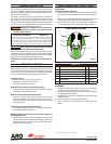
PUMP CONNECTION - UPPER / LOWER
DISASSEMBLY
NOTE: All threads are right hand.
Loosen the (90571) lock nut and unscrew the entire pump from
the air motor. This will expose the (6) connector pin (see gure
2).
Remove the (5) retaining ring and (6) connector pin to release
the air motor piston rod from the lower pump piston rod.
Remove (4) spacer, (2) washer, four (3) packings, (2) washer and
(1) wavy spring washer from the air motor cavity (see gure 2).
65968 Adapter Kit Assembly
1
3
5
2
4
6
Figure 2
PARTS LIST
Item Description
(size)
Qty Part No.
1 Wavy Spring Washer (1) 90251
2 Washer (2) 90568
3 Packing (4) 90567
4 Spacer (1) 90570
5 Retaining Ring (1) Y145-2
6 Connector Pin (1) 90572
REASSEMBLY
Assemble (1) wavy spring washer, (2) washer, four (3) packings,
(2) washer and (4) spacer into cavity in the air motor.
Assemble the lower pump piston rod to the air motor piston
rod, aligning the through holes.
Assemble the (6) connector pin through the hole, securing with
(5) retaining ring.
Screw the lower pump assembly to the air motor.
Screw the (90571) lock nut against the air motor base and
tighten.
1.
2.
3.
1.
2.
3.
4.
5.
y
ARO® is a registered trademark of Ingersoll-Rand
y