


650929-X
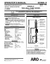
PUMP OPTION DESCRIPTION CHART
650929--X
PACKING MATERIAL
PLUNGER TYPE
SPRING ARRANGEMENT
PACKING MATERIAL (PACKINGSAREUPPERANDLOWERUNLESSNOTED)
3 GLASSFILLEDPTFE P UHMW--PE/PTFE STAG’D (UPPER)
C UHMW--PE UHMW--PE(LOWER)
G UHMW--PE/LEATHERSTAG’D R PTFE/UHMW--PESTAG’D(UPPER)
PTFE(LOWER)
SPRING ARRANGEMENT
4
MULTIPLEWAVESPRING
PLUNGER TYPE
3
HDSS W/HDCHROMEPLATING
43
GENERAL DESCRIPTION
WARNING
HAZARDOUS PRESSURE. Do not exceed maxi-
mum operating pressure of 2054 psi (142 bar) at 1200 psi (83
bar) inlet hydraulic pressure.
PUMP RATIO X MAXIMUM PUMP
INLET PRESSURE TO PUMP MOTOR
= FLUID PRESSURE
Pumpratiois anexpressionofthe relationshipbetweenthe pumpmotorareaandthe
lowerpumpendarea.EXAMPLE:When150p.s.i.(10.3bar)inletpressureissupplied
tothemotorofa5:1ratiopumpitwilldevelopamaximumof750p.s.i.(52bar)fluidpres-
sure(atnoflow)--asthefluidcontrolisopened,theflowratewillincreaseasthemotor
cycle rate increases to keepup withthe demand.
WARNING
Refer to general information sheet for additional
safety precautions and important information.
• The Two--Ballpumps areprimarilydesignedfor the pumpingofme-
dium viscosityfluids compatible withcarbon steel. T helower pump
is designed for easy priming and the double acting feature is stan-
dard in all ARO industrial pumps. Material is delivered to thepump
discharge outlet on both the up and down stroke.
• The motoris connectedto thelower pumpend byaspacer section.
This allows for lubrication of the upper packinggland and prevents
motorcontaminationbecauseofnormalwearandeventualleakage
through thematerial packinggland. Besure the solvent cupis ade-
quatelyfilled with lubricant toprotecttheupper packingsandinsure
longest service life.
TROUBLE SHOOTING
Pump problems can occur in either the Hydraulic Motor Section or the
LowerPump EndSection,use these basicguidelinestohelpdetermine
which section is affected.
If the pump will not cycle.
• Be certain to first check for non--pump problems including kinked,
restrictiveorpluggedinlet/outlethoseordispensingdevice.Depres-
surize the pumpsystem and clean outany obstructions inthe inlet/
outlet material lines.
• Refer tothe motormanual fortroubleshooting ifthe pumpdoesnot
cycle and/or hydraulic fluid leaks from the hydraulic motor.
If the pump cycles but does not deliver material.
• Refer to the lower pump end manual for further trouble shooting.
PUMP CONNECTION -- UPPER / LOWER
NOTE: All threads are right hand.
1. Lay the pump assembly on a workbench.
2. Remove the three screws andwashers from the three spacer rods
(see figure 1).
3. Pull thehydraulicmotor fromthe lower pumpend untilmotor piston
rodis inthe‘‘down” positionandlower pumpendrod is in ‘‘up”posi-
tion.
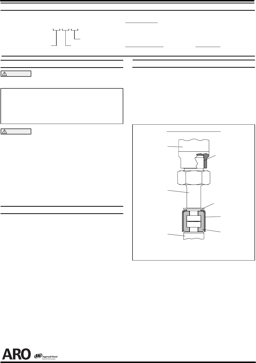
4. Usinge--ringpliers,slidetheretainingringupfarenoughtoallowthe
sleeve tomove upward and releasethe two connectors (see figure
2).
Lower Pump
Piston Rod
Pump Motor
Piston Rod
Retaining Ring
90102
Sleeve
90109
Connector
90096 (2)
PUMP CONNECTOR DETAIL
FIGURE 2
Adapter
93344--1
APPLY LOCTITE
271
REASSEMBLY
1. Align the pump motor with the lower pump end.
2. Installthetwoconnectorsandretainwiththesleeve,slidetheretain-
ing ring back into position.
3. Reinstall the spacer rods to the pump motor.
4. Bring the motor and lower pump together and retain with the three
screws and washers.
PN 97999-329