


650925-X-B
PUMP OPTION DESCRIPTION CHART
650925--X
SPRING ARRANGEMENT
MODEL REVISION
PLUNGER TYPE
PACKING MATERIAL (PACKINGSAREUPPERANDLOWERUNLESSNOTED)
7 GLASS FILLEDPTFE (UPPER) P UHMW--PE /PTFESTAG’D(UPPER)
VIRGINPTFE (LOWER
) UHMW--P E (LOWER)
C UHMW--PE R PTFE /UHMW--PE STAG’D (UPPER)
F UHMW--PE /LEATHERSTAG’D(UPPER) PTFE (LOWER)
UHMW--PE (LOWER)
SPRING ARRANGEMENT
4
MULTIPLE WAVESPRING
PLUNGER TYPE
3
HD SSW/HD CHROMEPLATING
43--B
PACKING MATERIAL
GENERAL DESCRIPTION
WARNING
HAZARDOUS PRESSURE. Do not exceed maxi-
mum operatingpressure of360psi (25bar) at1200 psi(83 bar)
inlet hydraulic pressure.
PUMP RATIO X MAXIMUM PUMP
INLET PRESSURE TO PUMP MOTOR
= FLUID PRESSURE
Pump ratiois anexpressionof therelationship betweenthe pumpmotorarea andthe
lowerpumpend area.EXAMPLE:When150p.s.i. (10.3bar)inletpressureissupplied
tothemotorofa5:1ratiopumpitwilldevelopamaximumof750p.s.i.(52bar)fluidpres-
sure(atnoflow)--asthefluidcontrolisopened,theflowratewillincreaseasthemotor
cycle rate increases to keep upwith the demand.
WARNING
Refer to general information sheet for additional
safety precautions and important information.
• The Four--Ball pumps are primarily designed for the high volume
transfer oflight andmedium viscosityfluids compatiblewith 400se-
ries stainless steel. The lower pump is designed for easy priming
and the double acting feature is standard in all ARO industrial
pumps. Material is delivered to the pump discharge outlet on both
the up and down stroke.
• The motor isconnected tothe lower pumpend bya spacer section.
This allows for lubrication of the upper packing gland andprevents
motorcontaminationbecause ofnormalwearand eventualleakage
through thematerial packing gland.Be surethe solvent cupis ade-
quately filledwithlubricant toprotectthe upperpackings andinsure
longest service life.
TROUBLE SHOOTING
Pump problems can occur in either the Hydraulic Motor Section or the
Lower PumpEnd Section,use these basicguidelines tohelpdetermine
which section is affected.
If the pump will not cycle.
• Be certain to first check for non--pump problems including kinked,
restrictive or plugged inlet / outlet hose or dispensing device. De-
pressurize the pump system and clean out any obstructions in the
inlet / outlet material lines.
• Refer tothe motormanual fortrouble shooting if thepump doesnot
cycle and / or hydraulic fluid leaks from the hydraulic motor.
If the pump cycles but does not deliver material.
• Refer to the lower pump end manual for further trouble shooting.
PUMP CONNECTION -- UPPER / LOWER
NOTE: All threads are right hand.
1. Lay the pump assembly on a workbench.
2. Remove the three screws and washersfrom the three spacer rods
(see figure 1).
3. Pull thehydraulic motorfrom thelower pump enduntil motorpiston
rod is in the‘‘down” positionand lowerpump endrodis in ‘‘up” posi-
tion.
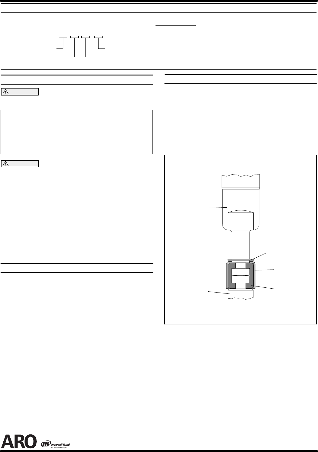
4. Usinge--ringpliers,slidetheretainingringupfarenoughtoallowthe
sleeve to moveupward and release thetwo connectors (seefigure
2).
Lower Pump
Piston Rod
Pump Motor
Piston Rod
Retaining Ring
91547
Sleeve
91546
Connector
91644 (2)
PUMP CONNECTOR DETAIL
FIGURE 2
REASSEMBLY
1. Align the pump motor with the lower pump end.
2. Installthetwoconnectorsandretainwiththesleeve,slidetheretain-
ing ring back into position.
3. Reinstall the spacer rods to the pump motor.
4. Bring the motor and lower pump together and retain with the three
screws and washers.
PN 97999-734