


Page 2 of 4 650542-X (en)
OPERATING INSTRUCTIONS / INITIAL SET-UP PROCEDURE
WARNING
Stand clear when raising or lowering the
lift. Read the warnings on page 2 of 651615-X-D Single
Post Lift / Ram Operator’s Manual (pn 97999-1025).
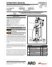
AIR CONTROLS
“D”
“E”
“F”
“G”
“A”“B”“C”
Follower Plate
Air Supply Valve
A - Pump Regulator
B - Pump Pressure Gauge
C - Pump Air Supply Valve
D - Air Supply
E - Lift / Ram Pressure Gauge
F - Lift / Ram Pressure Regulator
G - Follower Plate Air Supply Valve
Figure 2
TO RAISE THE LIFT, (the rst time):
Take note of the pump / drum clearance above. Be cer-
tain the lift / ram is clear of any objects above. Also, refer
to “Operating and Safety Precautions” found in “Lifts and
Rams General Information Manual” (pn 97999-635).
Connect the air supply (150 p.s.i. / 10.3 bar maximum) to
the air inlet. Adjust the air pressure on the lift / ram pres-
sure regulator (turn the knob clockwise) to 20 p.s.i. (1.4
bar).
Shift the control valve lever to the “up” position.
Raise the lift / ram high enough to clear the height of the
drum. Stop the lift / ram’s upward travel by moving the
control valve lever to the “neutral” (center) position.
REFER TO PAGE 3:
Once the lift / ram assembly and pump are in the “up”
position, place and center an opened 5 gallon / 25 liter
1.
2.
3.
4.
1
.
INSTALLATION
The 65054X-X Extrusion System comes completely assem-
bled. Remove the unit from the crate and place on a level
surface. Install the material hose and dispensing device as
required.
When the following instructions are observed, heavy paste
materials can be pumped directly from their original 5 gallon
/ 25 liter drum without air inclusion or excessive waste. The
follower plate creates an air tight seal as well as clean-wiping
action in its progressive downward movement into the drum.
OPERATING INSTRUCTIONS
drum of material on the lift / ram base. Use the stops on
the base to center the 5 gallon / 25 liter drum. Tighten
the thumb screw to secure the drum.
Lubricate the lower follower wiper plate seal with grease.
This ensures a smooth t into the drum, as well as pre-
vents curing type compounds from bonding to the seal.
NOTE: Make certain the grease is compatible with the
material being dispensed.
Check the vent plug on the follower plate to be sure it
easily threads in and out. It is recommended to lubricate
the threads of the plug to help prevent possible set-up
of the compound at this point (see 65184X-X Operator’s
Manual).
TO LOWER LIFT:
WARNING
PINCH HAZARD. Follower can descend
quickly, causing injury. Keep hands clear when align-
ing with container. Read the warnings in “Lifts and Rams
General Information Manual” (pn 97999-635).
NOTE: Be certain the follower plate vent plug has been re-
moved so that the air trapped between the follower and the
material is allowed to escape from this vent. Captured air
between the follower plate and drum will escape.
NOTE: The lift / ram may hesitate momentarily before start-
ing downward. The air pressure inside the post air chamber
must decrease before it will begin to descend.
Shift the control valve lever to the “down” position and
proceed to lower the pump.
Replace the vent plug once the material begins to ooze
from the vent opening.
The unit is now ready for operation. Adjust the air pres-
sure on the pump lter / regulator (turn the pump regu-
lator knob clockwise) until the pump begins to cycle.
Trigger the gun to prime the pump with material.
TO RAISE LIFT, (normal operation):
Adjust the follower plate air valve pressure up to approx-
imately 8 p.s.i.g. (0.55 bar). DO NOT OVER PRESSURIZE
THE DRUM to avoid damage. NOTE: Air from this valve
will only pass when the control valve lever is in the “up”
position.
Shift the control valve lever to the “up” position.
Raise the lift / ram high enough to clear the height of the
drum. Stop the lift / ram’s upward travel by moving the
control valve lever to the “neutral” (center) position.
TO CHANGE THE DRUM:
NOTE: The control valve lever must be in the “neutral” posi-
tion.
Unscrew the thumb screw and remove the old 5 gallon /
25 liter drum.
Place and center a new drum into position. Remove the
cover. Tighten the thumb screw.
2.
3.
1.
2.
3.
4.
1.
2.
3.
1.
2.