


PAGE2OF4 650501-B
PARTS LIST / 650501–B
Item Description (Size in inches)
(Qty)
Part No. Item Description (Size in inches)
(Qty)
Part No.
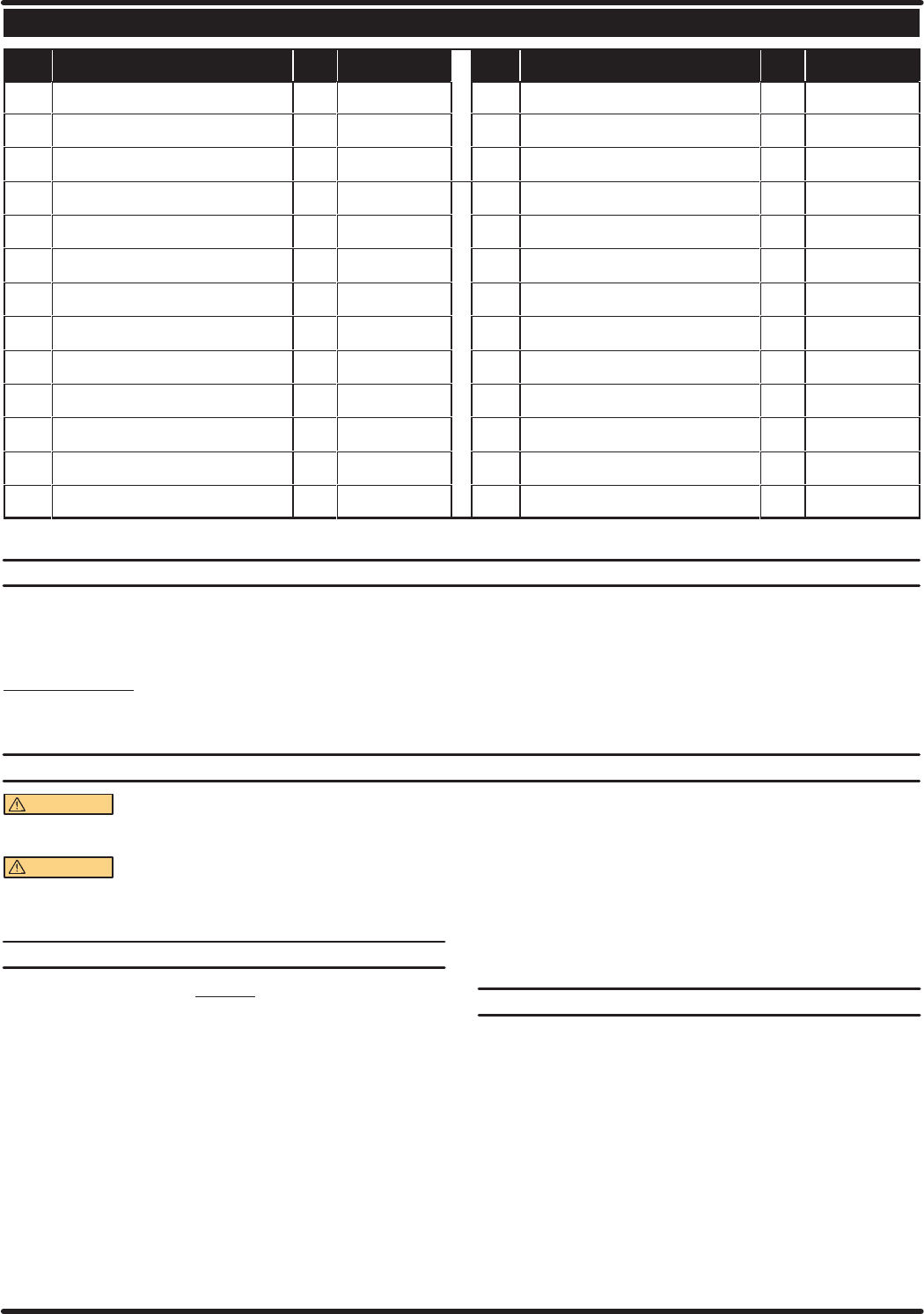
1 Bracket (1) 94040
14 Male Elbow (1/4"o.d.tube - 1/4"-18male thd) (2) 59745-156
2 Adapter (3/8"-18 male x 1/4"-18 male) (1) 90538 15 Bracket (1) 93839
3 Adapter (1/4" - 18 NPTF) (3) 1950 16 Tubing (1/4" o.d. x 8-1/2'' long) (1) 59675-100 f
4 Connector (1) 23902-210 17 Bolt (1/4" - 20 x 1") (4) Y6-45-T
5 Gauge (0 - 60 p.s.i.) (1) 100090 18 Washer (.281" i.d. x .625" o.d.) (4) 93096
6 Gauge (0 - 160 p.s.i.) (1) 100091 19 Nut (1/4" - 20) (4) Y12-4-S
7 Coupling (1/4" - 18 NPT) (1) Y43-42-C 20 Tube (6' long) (1) 59840-62
8 Tee (1/4" - 18 NPTF) (1) 94039 21 Elbow (1) 94043
9 Gauge (0 - 30 p.s.i.) (1) 93769 22 Tube (36" long) (1) 93320
10 Adapter (1) 94511 23 Nut (1) 94036
11 Tube (12'' long) (1) 628091-1 24 Roll Pin (.094" o.d. x .250" long) (1) Y178-18-S
12 Nut (2) 100022 25 Elbow (1/4" - 18 NPTF) (1) 94044
13 Coupler (1) 23102-200 26 Ground Kit Assembly (not shown) (1) 66885-1
fTube is available inbulk quantities only.
GENERAL DESCRIPTION (CONTINUED)
Consult your sales representative for the proper low pressure gun and
other accessories which will best match the application.
This system includes a wall mount bracket which can also be attached
to cart pn 67074.
Theory of operation:
HVLP (High Volume, Low Pressure) is a spray process which uses a
high volume of air(15 - 22 c.f.m.) at a low pressure(10 p.s.i. or less) to
atomize the material, producing both high transfer efficiency (the total
percent of material that actually stays on the intended surface) and a
quality finish.Theair capofthe HVLP gun injects airintothe fluid after it
passes through the orifice restriction. The low velocity of the material
being sprayed minimizes the over-spray and bounce-back that is asĆ
sociated with conventional air spray.
OPERATING INSTRUCTIONS
WARNING
DO NOT EXCEEDMAXIMUM OPERATING PRESĆ
SUREOF 100 P.S.I.(6.9 BAR)AT 100P.S.I. (6.9 BAR) AIR INLET
PRESSURE.
WARNING READ THE PUMP MANUAL FOR ADDITIONAL
OPERATING AND SAFETY PRECAUTIONS AND OTHER IMĆ
PORTANT INFORMATION.
INITIAL
SETUP PROCEDURE
NOTICE
REFER TO THE INFORMATION INCLUDED WITHTHE LOW PRESĆ
SURE HVLP GUN FOR SYSTEM SETUP INFORMATION. THE SYSĆ
TEM IS INTENDED FOR LOW PRESSURE APPLICATION ONLY.
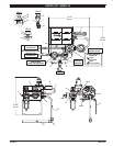
• Attach air supply hose, gun and low pressure material hose.
• Install the connector to the air supply hose.
• Attach the ground wire to a suitable ground.
• The gun air supply hose must be 5/16'' i.d. minimum.
• Keep containers covered to prevent contamination.
Nominal system settings:
• Pump Outlet Material Pressure - 15 p.s.i. maximum.
• Spray Gun Air Pressure - 60 p.s.i. maximum. Note: At 30 p.s.i.
nominal setting it will deliver approximately 8 p.s.i. at the air cap
when using 5/16" i.d. x 15' long air hose.
• Set air pressure to the pump at approximately 2x (two times) the
operating material pressure.
For example: If 15 p.s.i. material pressure is required, adjust the
pump air regulator/gauge pressure to approximately 30 p.s.i.
Use the material pressure regulator to adjust. Control the spray
gun air volume using the air regulator.
START–UP
1. Turn the knob on the air regulator counterclockwise to zero p.s.i.
2. Place (22) tube into the container of material.
3. Theoperating pressureshould be set atthe lowest needed toatomĆ
ize anddeliver the paint. Start withthe gunmaterial pressure about
the same asthe airsupply and adjustup ordown toset the pattern.
4. Start the pump to cycleby turning the air regulator knob clockwise.
The pump will cycle several strokes until pressure is built up in the
system, at which time it will stop. Check for any loose fittings or
leakage.