


650435-X-C
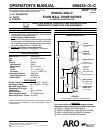
PUMP OPTION DESCRIPTION CHART
650435--X
PACKING MATERIAL
PLUNGER TYPE
SPRING ARRANGEMENT
PACKING MATERIAL(PACKINGSAREUPPERAND LOWERUNLESSNOTED)
7 GLASS FILLEDPTFE (UPPER) P UHMW--PE/PTFE STAG’D(UPPER)
VIRGINPTFE (LOWER
) UHMW--PE(LOWER)
C UHMW--PE R PTFE/UHMW--PESTAG’D(UPPER)
F UHMW--PE/LEATHER STAG’D(UPPER) PTFE (LOWER)
UHMW--PE(LOWER)
SPRING ARRANGEMENT
4
MULTIPLE WAVESPRING
PLUNGER TYPE
6
SS W/HDCHROME PLATING
46--C
GENERAL DESCRIPTION
WARNING
HAZARDOUS PRESSURE. Do not exceed maxi-
mum operating pressure of 300 psi (20.7 bar) at 150 psi (10.3
bar) inlet air pressure.
PUMP RATIO X MAXIMUM PUMP
INLET PRESSURE TO PUMP MOTOR
= FLUID PRESSURE
Pump ratiois anexpressionof therelationship betweenthe pumpmotorarea andthe
lowerpumpend area.EXAMPLE:When150p.s.i. (10.3bar)inletpressureissupplied
to the motorof a2:1 ratiopump it will developa maximum of300 p.s.i.(20.7 bar)fluid
pressure(at noflow) -- asthe fluid controlis opened,the flow ratewill increase asthe
motor cycle rate increases to keepup with the demand.
WARNING
Refer to general information sheet for additional
safety precautions and important information.
• The Four--Ball pumps are primarily designed for the high volume
transfer oflight andmedium viscosityfluids compatiblewith 300se-
ries stainless s teel. The lower pump is designed for easy priming
and the double acting feature is standard on all ARO industrial
pumps. Material is delivered to the pump discharge outlet on both
the up and down stroke.
• The motor isconnected tothe lower pumpend bya spacer section.
This allows for lubrication of the upper packing gland andprevents
motorcontaminationbecause ofnormalwearand eventualleakage
through thematerial packing gland.Be surethe solvent cupis ade-
quately filledwithlubricant toprotectthe upperpackings andinsure
longest service life.
TROUBLE SHOOTING
Pump problems can occur in either the A ir Motor Section or the Lower
Pump EndSection. Usethese basicguidelines tohelp determinewhich
section is affected.
If the pump will not cycle.
• Be certain to first check for non--pump problems including kinked,
restrictiveorpluggedinlet/outlethoseordispensingdevice.Depres-
surize the pump systemand clean outany obstructions in theinlet/
outlet material lines.
• Refer tothe motormanual fortrouble shooting if thepump doesnot
cycle and/or air leaks from the air motor.
If the pump cycles but does not deliver material.
• Refer to the lower pump end manual for further trouble shooting.
PUMP CONNECTION -- UPPER / LOWER
NOTE: All threads are right hand.
1. Lay the pump assembly on a workbench.
2. Removethethreenutsandwashersfromthethreespacerrods(see
figure 1).
3. Pulltheairmotorfromthelowerpumpenduntilmotorpistonrodisin
the ‘‘down” position and lower pump end rod is in ‘‘up” position.
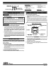
4. Usinge--ringpliers,slidetheretainingringupfarenoughtoallowthe
sleeve to moveupward and release thetwo connectors (seefigure
2).
Lower Pump
Piston Rod
Pump Motor
Piston Rod
RETAINING RING
91547
SLEEVE 91546
CONNECTOR
91644 (2)
PUMP CONNECTOR DETAIL
FIGURE 2
REASSEMBLY
1. Align the pumpmotorwith thelower pumpend. Positiontheair inlet
of the motor 200_ from the material outlet.
2. Installthetwoconnectorsandretainwiththesleeve,slidetheretain-
ing ring back into position.
3. Reinstall the spacer rods to the pump motor.
4. Bring the motor and lower pump together and retain with the three
nuts and washers.
PN 97999-689