


PN 97999-581
650409-XPage2of2
PUMP OPTION DESCRIPTION CHART
650409 - X
DESCRIPTION
PTFE Packing / Plain Rod & Tube, Standard Motor
1 UHMW-PE Packing / Plain Rod & Tube, Counter Motor
4 UHMW-PE Packing / Plain Rod & Tube, Standard Motor
DESCRIPTION
GENERAL DESCRIPTION
WARNING
HAZARDOUS PRESSURE. Do not exceed maxi-
mumoperating pressureof1,350 p.s.i.(93bar) at150p.s.i. (10.3
bar) inlet air pressure.
PUMP RATIO X MAXIMUM PUMP
INLET PRESSURE TO PUMP MOTOR
= FLUID PRESSURE
Pump ratio is an expression of the relationship between the pump motor area and the
lower pump endarea. EXAMPLE: When 150p.s.i. (10.3 bar)inlet pressure issupplied
to the motor of a 9:1 ratio pump it will develop a maximum of 1,350 p.s.i. (93 bar) fluid
pressure (at no flow) - as the fluid control is opened, the flow rate will increase as the
motor cycle rate increases to keep up with the demand.
WARNING
Refer to general information sheet for additional
safety precautions and important information.
• Thetwo-balldesign providesfor easypriming ofthelower footvalve.
The double acting feature is standard in all ARO industrial pumps.
Material isdelivered tothe pumpdischarge outlet onboth theup and
down stroke.
• The motor is connected to the lower pump end with a spacer tube
and solvent cup. This allows for lubrication of the upper packing
gland and to prevent air motor contamination because of normal
wear and eventual leakage through the material packing gland.
TROUBLE SHOOTING
Pump problems can occur in either the air motor section or the lower
pump end section. Use these basic guidelines to help determine which
section is affected. Be sure to eliminate any possible non-pump prob-
lems before suspecting pump malfunction.
Pump will not cycle.
• No pressure to the motor. See motor manual.
• Restricted return lines. Clean obstruction.
• Damaged motor. Service motor
No material at the outlet (pump continually cycles).
• Check the material supply, disconnect or shut off the air supply and
replenish the material, reconnect.
Material on one stroke only (fast downstroke).
• The lower check may not be seating in the foot valve (see lower
pump disassembly). Remove the check from the foot valve, clean
and inspect the valve seat area. If check or foot valve are damaged,
replace.
Material on one stroke only (fast upstroke).
• The middle packings may be worn (see lower pump disassembly).
Replace the seals as necessary.
Material leakage out of the solvent cup or material appears on the
pump plunger rod.
• Tighten the solvent cup until leakage discontinues. If this procedure
does not aid in stopping the leakage problem, the upper packings
may be worn (see lower pump disassembly). Replace the seals as
necessary.
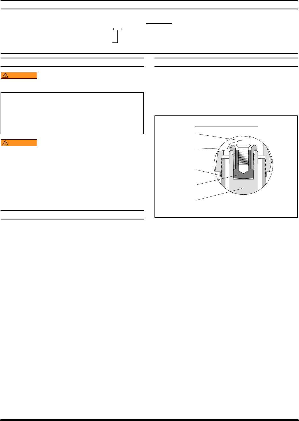
PUMP CONNECTION - UPPER / LOWER
NOTE: All threads are right hand.
1. Loosen (90606) lock nut and unscrew entire pump from the air mo-
tor. This will expose (90609) retaining screw (see figure 2).
2. Unscrew (90609) retaining screw to remove pump assembly from
the air motor.
3. Remove (90608) shoulder nut to remove (90609) retaining screw.
Lower Pump
Plunger
Pump Motor
Piston Rod
PUMP CONNECTOR DETAIL
Figure 2
Shoulder Nut
90608
Lock Nut
(90606) Ref.
Retaining Screw
90609
REASSEMBLY
1. Slide (90609) retaining screw over air motor rod (see figure 2).
2. Screw (90608) shoulder nut to air motor rod.
3. Apply Loctite 242 to threads of (90609) retaining screw and screw
(90609) retaining screw into lower pump plunger.
4. Screw the lower pump assembly to the air motor.
5. Position air motor exhaust port approximately 90_ from lower pump
outlet.
6. Screw (90606) lock nut against air motor base and tighten to 50 - 65
ft lbs (67.8 - 88.1 Nm).