


650385-X
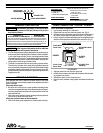
PUMP OPTION DESCRIPTION CHART
650385--X
PACKING MATERIAL
PLUNGER TYPE
SPRING ARRANGEMENT
(PACKINGSAREUPPERANDLOWERUNLESSNOTED)
PACKING MATERIAL
P
UHMW--PE/PTFESTAG’D(UPPER)
UHMW--PE(LOWER)
SPRING ARRANGEMENT
4 MULTIPLEWAVE SPRING
PLUNGER TYPE
3 HD SS W/HDCHROME PLATING
B HD SS W/CERAMICCOATING
3 GLASSFILLED PTFE
C UHMW--PE
G UHMW--PE/LEATHER STAG’D
R
PTFE/UHMW--PESTAG’D(UPPER)
PTFE(LOWER)
4X
GENERAL DESCRIPTION
WARNING
HAZARDOUS PRESSURE. Do not exceed maxi-
mum operating pressure of 2550 psi (176 bar) at 150 psi (10.3
bar) inlet air pressure.
PUMP RATIO X
INLET PRESSURE TO PUMP MOTOR
=
MAXIMUM PUMP
FLUID PRESSURE
Pumpratioisanexpressionoftherelationshipbetweenthepumpmotorareaand
thelower pumpendarea.EXAMPLE: When150p.s.i.(10.3 bar) inlet pressureis
suppliedtothemotorofa6:1ratiopumpitwilldevelopamaximumof750p.s.i.(52
bar)fluidpressure(atnoflow)--asthe fluidcontrolisopened,theflowratewillin-
crease asthe motor cycle rateincreases to keepup withthe demand.
WARNING
Refer to general information sheet for additional
safety precautions and important information.
• TheTwo--Ballpumps areprimarilydesignedfor the pumpingofme-
diumviscosityfluids,StainlessSteelconstructionofferscompatibili-
ty with a wide range of fluids. The two--ball design provides better
primingofthelowerfootvalve.Thedoubleactingfeatureisstandard
in all ARO industrial pumps, material is delivered to the pump dis-
charge outlet on both the up and down stroke.
• The motor isconnected to thelower pumpend bya spacer section.
This allows for lubrication of the upper packinggland and prevents
motorcontaminationbecauseofnormalwearandeventualleakage
through thematerial packinggland. Besure the solvent cupis ade-
quatelyfilled with lubricant toprotecttheupper packingsandinsure
longest service life.
TROUBLE SHOOTING
Pump problems can occur in either the Air Motor Section or the Lower
Pump EndSection, usethese basicguidelinesto help determinewhich
section is affected.
If the pump will not cycle.
• Be certain to first check for non--pump problems including kinked,
restrictiveorpluggedinlet/outlethoseordispensingdevice.Depres-
surize the pumpsystem and clean outany obstructions inthe inlet/
outlet material lines.
• Refer tothe motormanualfor troubleshooting if thepump doesnot
cycle and/or air leaks from the air motor.
If the pump cycles but does not deliver material.
• Refer to the lower pump end manual for further trouble shooting.
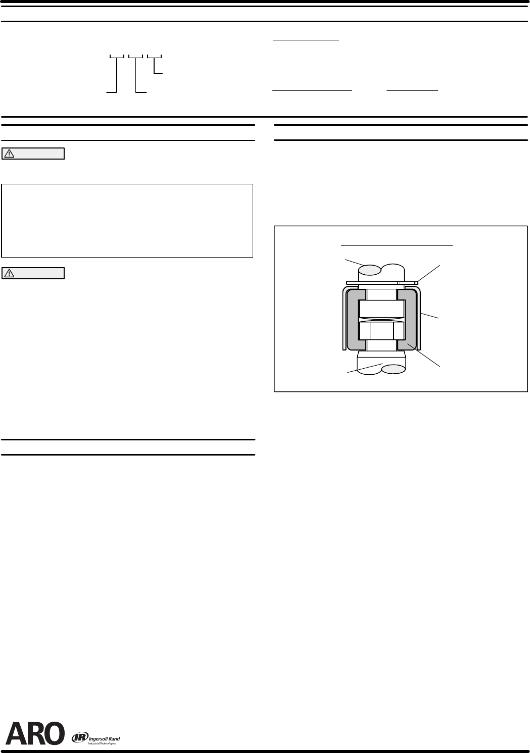
PUMP CONNECTION -- UPPER / LOWER
NOTE: All threads are right hand.
1. Lay the pump assembly on a workbench.
2. Remove the three nuts from the three spacer rods. (Fig. 1)
3. Pulltheairmotorfromthelowerpumpenduntilmotorpistonrodisin
the ‘‘down” position and lower pump end rod is in ‘‘up” position.
4. Usinge--ringpliers,slidetheretainingringupfarenoughtoallowthe
sleeve to move upward and release the two connectors. (Fig. 2)
Lower Pump
Piston Rod
Pump Motor
Piston Rod
RETAINING RING
90102
SLEEVE
90109
CONNECTOR
90096 (2)
PUMP CONNECTOR DETAIL
FIGURE 2
REASSEMBLY
1. Align the pump motor with the lower pump end.
2. Installthetwoconnectorsandretainwiththesleeve,slidetheretain-
ing ring back into position.
3. Reinstall the spacer rods to the pump motor.
4. Bring the motor and lower pump together and retain with the three
nuts.
PN 97999-651