


Page 2 of 2 650311-X & 650312-X (en)
PN 97999-1588
GENERAL DESCRIPTION
Model 65031X-X Series two-ball, double acting pumps are intended
to be used primarily for oil transfer and delivery systems. It is best to
use this pump with low -- medium viscosity uids. It uses Stainless
steel and other materialswhich make it compatible with most petro-
leum based lubrication products. The two-ball design provides bet-
ter priming of the lower foot valve. Double acting pumpswill deliver
material on both the up and down stroke.
NOTE: If this pump was purchased separately (not part of a system),
consult your sales representative for compatible dispensing acces-
sories which will best match the application. All accessories must be
able to withstand the maximum pressure developed by the pump.
WARNING
HAZARDOUS PRESSURE. Do not exceed maxi-
mum operating pressure of 343 p.s.i. (23.6 bar) at 150 p.s.i.
(10.3 bar) inlet hydraulic pressure.
Pump Ratio X = Maximum Pump
Inlet Pressure to Pump Motor Fluid Pressure
Pump ratio is an expression of the relationship between the pump motor area
and the lower pump end area. EXAMPLE: When 150 p.s.i. (10.3 bar) inlet pressure
is supplied to the motor of a 4:1 ratio pump, it will develop a maximum of 600
p.s.i. (41.4 bar) uid pressure (at no ow) - as the uid control is opened, the ow
rate will increase as the motor cycle rate increases to keep up with the demand.
WARNING
Refer to general information sheet for additional
safety precautions and important information.
NOTICE: Thermal expansion can occur when the uid in the mate-
rial lines is exposed to elevated temperatures. Example: Material
lines located in a non-insulated roof area can warm due to sunlight.
Install a pressure relief valve in the pumping system.
Replacement warning label (pn 94520) is available upon request.
TROUBLE SHOOTING
Pump problems can occur in either the Air Motor Section or the
Lower Pump End Section. Use these basic guidelines to help deter-
mine which section is affected. Be sure to eliminate any possible
non-pump problems before suspecting pump malfunction.
Pump will not cycle.
No pressure to the motor. See motor manual.
Damaged motor. Service motor.
No material at the outlet (pump continually cycles).
Check the material supply, disconnect or shut o the air supply
and replenish the material, reconnect.
Material on one stroke only (fast downstroke).
The lower check may not be seating in the foot valve (see lower pump
disassembly). Remove the check from the foot valve, clean and in-
spect the valve seat area. If check or foot valve are damaged, replace.
Material on one stroke only (fast upstroke).
The middle packings may be worn (see lower pump disassem-
bly). Replace the seals as necessary.
PUMP CONNECTION - UPPER / LOWER
NOTE: All threads are right hand.
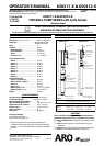
Loosen (90606) lock nut and unscrew the entire pump from
the air motor. This will expose (94445) adapter (see gure 2).
Unscrew (94445) adapter to remove pump assembly from the
air motor.
1.
2.
Remove the (Y15-21) cotter pin and (94048) clevis pin to
remove (94445) adapter.
Pump Motor Piston Rod
PUMP CONNECTION DETAIL
Figure 2
Y15-21 Cotter Pin
Lower Pump Plunger
90606 Lock Nut (ref.)
94048 Clevis Pin
94445 Adapter
REASSEMBLY
Assemble (94445) adapter to the air motor rod, aligning the
through holes.
Assemble (94048) clevis pin through hole, securing adapter.
Assemble (Y15-21) cotter pin through the hole in the clevis pin.
Apply Loctite® 242 to threads of (94445) adapter and screw
(94445) adapter into (90615-X) plunger.
Screw the lower pump assembly to the air motor.
Screw (90606) lock nut against the air motor base and tighten
to 50 - 60 ft. lbs (67.8 - 81.3 Nm).
OPERATION - SENSOR
Maximum Operating Voltage - 200VDC.
Switching Current -0.5 Amps.
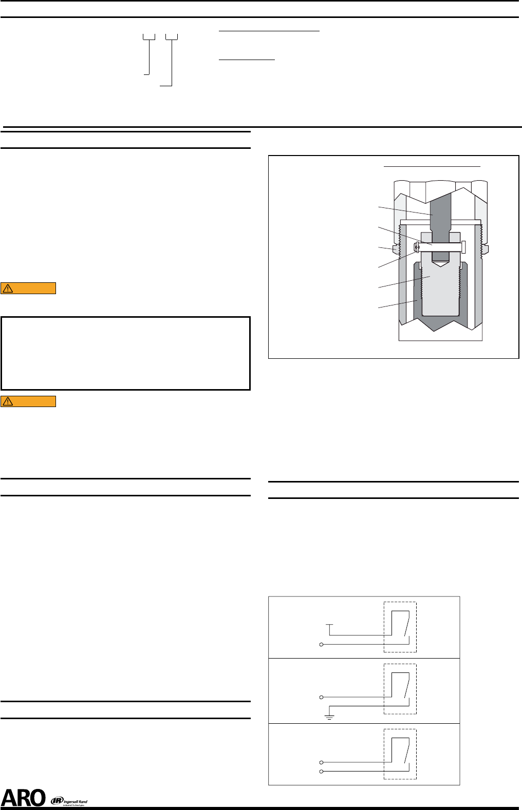
Once the kit is installed in the pump, it may be interfaced with a
control device in the following ways:
As a SOURCING switch (see gure 3) for use with PLC’s.
As a SINKING switch (see gure 4) for use with PLC’s.
As a closed contact switch (see gure 5) for use with meters.
INPUT
INPUT
INPUTS
Figure 3
Figure 4
Figure 5
+V
Sourcing Switch
Sinking Switch
Closed ContactSwitch
3.
1.
2.
3.
4.
5.
6.
PUMP OPTION DESCRIPTION CHART
65031- X - X
Container Suitability
Description
CONTAINER SUITABILITY
1 - Universal (stub)
2 - 55 Gallon
DESCRIPTION
- PTFE packing (upper and lower)/ Plain Rod & Tube
4 - UHMW-PE packing(upper and lower) / Plain Rod & Tube
5 - PTFE packing (upper and lower) / Ceramic Coated Rod & Tube
6 - UHMW-PE packing(upper and lower) / Ceramic Coated Rod & Tube
7 - Viton packing(upper)/UHMW-PE packing (lower)/ Ceramic Coated Rod & Tube
8 - Viton packing(upper)/PTFE packing (lower)/ Plain Rod & Tube
9 - Viton packing(upper)/UHMW-PE packing (lower)/ Plain Rod & Tube