


PAGE 2 OF 4
66172-X
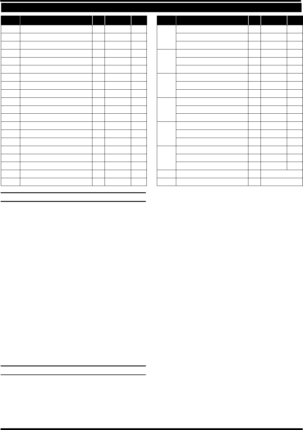
PARTS LIST
ITEM DESCRIPTION (Sizein Inches)
QTY
PART NO. [MTL] ITEM DESCRIPTION (Sizein Inches)
QTY
PART NO. [MTL]
1 Plunger (1) 90297-1 [SS]
2 Solvent Cup (1) 66009 [C]
3 Female Washer (1) 90029 [SS]
4 Washer , Male Backup (1) 90031 [SS]
g 5 Spring (1) 90008 [SS]
6 Pump Body (1) 91467 [C]
gn 7 Gasket (3) 92840 [SS]
8 Locking Nut (2) 90027 [SS]
9 W asher (1) 90587 [C]
g 10 Bowed Spring Washer (2) 90588 [SS]
11 Washer , Male Backup (2) 90591 [SS]
12 Washer, Female Backup (2) 90590 [SS]
n 13 Ball (.3437” o.d.) (1) Y16-111 [SS]
n 14 Seat (1) 92084 [Ca]
n 15 Inner Check Seat (1) 92083 [SS]
n 16 Adapter (1) 92082 [SS]
17 Tube (1) 91463-1 [SS]
n 18 Ball Stop & Pin Assembly (1) 65019
[C]
n 19 Ball (.8125” o.d.) (1) Y16-126
[SS]
n 20 Foot Valve (1) 66103 [C]
g 22 “V” P acking (66172 and 66172- 2) (3) 93687-1 [L]
(66172-1) (3) 93687-2 [GFT]
(66172-3) (3) 93687-4 [UH]
g 23 “V” P acking (66172) (3) 93687-1 [L]
(66172-1 and 66172- 2) (3) 93687-2 [GFT]
(66172-3) (3) 93687-4 [UH]
g 24 “V” P acking (66172 and 66172- 2) (2) 93688-1 [L]
(66172-1) (2) 93688-2 [GFT]
(66172-3) (2) 93688-4 [UH]
g 25 “V” P acking (66172) (3) 93688-1 [L]
(66172-1 and 66172- 2) (3) 93688-2 [GFT]
(66172-3) (3) 93688-4 [UH]
g 26 “V” P acking (66172 and 66172- 2) (1) 93688-1 [L]
(66172-1) (1) 93688-2 [GFT]
(66172-3) (1) 93688-4 [UH]
g 27 “V” P acking (66172) (2) 93688-1 [L]
(66172-1 and 66172- 2) (2) 93688-2 [GFT]
(66172-3) (2) 93688-4 [UH]
g Items included in Service Kit 637012-X
n Items included in Service Kit 637013
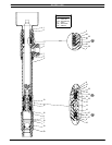
LOWER PUMP DISASSEMBLY
Note: All threads are right hand.
1. Vise the 66172 Lower Pump assembly on (6) pump body.
2. Unscrew (2) packing nut and remove.
3. Loosen (8) top lock nut. (The one next to (6) pump body.)
4. Securely hold (17) suction tube with a strop wrench and loosen (8)
lower lock nut. (The one next to (20) foot valve.)
5. Unscrew (20) foot valve assembly from the (17) suction tube.
6. Remove top (7) gasket, (18) ball stop and pin assembly, lower (7)
gasket, and (19) ball from (20) foot valve assembly.
7. Unscrew and remove (17) suction tube from (6) pump body and off
(1) plunger assembly. Now remove (7) gasket. NOTE: No need to
remove either (8) lock nut off (17) suction tube.
8. Push (1) plunger assembly down and out the bottom of (6) pump
body using caution not to mar or damage the finish on (1) plunger.
9. Fromthe(6) pumpbody,remove(3)female washer,(22and23) vee
packing, (4) male washer and (5) spring.
10. Remove (9) washer, (10) bowed spring washer, (11) male packing
washer, (24 and 25) (set of 5) packing and (12) female packing
washer.
11. Place a wrench on (15) check seat and remove from (16) adapter
which is still being held by t he vise.
12. Remove (13)ball and(14) seat.Remove (16) adapterfrom thevise.
13. Remove (12)female packingwasher, (26 and27) (setof3) packing,
(11 male packing washer and (10) bowed spring washer.
LOWER PUMP REASSEMBLY
NOTE: All rubber goods and packings should be lubricated with a com-
patible lubricant prior to assembly.
1. Place (5) spring, (4) male packing washer, (22 and 23) vee packing
and (3) female packing washer in (6) pump body.
2. Apply PTFE tape to the threads of (2) packing nut.
3. Screw (2) packing nut into (6) pump body. (Hand tight only.)
4. Assemble (10) bowed spring washer,(11)male backup washer (26
and 27) (set of 3) packing and (12) female backup washer to (16)
adapter.
CAUTION: When assembling packings and washers, be sure they
are assembled correctly as shown in Figure.
5. Assemble (12) female backup washer, (24 and 25) (set of 5) pack-
ing, (11) male backup washer, (10) bowed spring washer, and (9)
washer to (15) inner check seat.
6. ApplyLoctite242RemovableThreadlockertothreadsof(16) adapt-
er, then place (13) ball and (14) seat (bevel up) into position in (15)
inner check seat and screw (16) adapter into (15)inner check seat.
7. Grease (1) plunger, slowly and carefully slide (1) plunger (threaded
end) down through (2) packing nut, (22 and 23) packing and (6)
pump body.
8. Apply PTFE tape to threads of (15) inner check seat.
9. Screw (15) inner check seat into (1) plunger and tighten using the
wrench flats on plunger and the hex on the inner check seat.
10. Clean thethreads onboth endsof(17) suctiontubeand applyPTFE
tape to the threads.
11. Applygrease toinsideof(17)suctiontube andoverboth (24 and25)
and (26 and 27) packing assemblies.
12. Place (7) gasket with (6) pump body.
13. Slowly andcarefullyslide (17)suction tube (eitherend)over (24and
25) and (26 and 27) packing and (1) plunger assembly.
14. Screw (17) suction tube into (6) pump body and tighten with strap
wrench.
15. Place (19) ball, (7) gasket, (18) ball stop and pin assembly, and (7)
gasket into (20) foot valve.
16. Screw (20) foot valve onto the end of(17) suction tube and tighten.
17. Tighten both (8) lock nuts.
18. Tighten (2) packing nut.