


DISASSEMBLY
OPERATING
AND SAFETY PRECAUTIONS
REASSEMBLY
PAGE2OF4 2752X-X
• Read and heed all Warnings, Cautions, and Safety PrecauĆ
tions before operating this pump.
• Use only genuine ARO replacement parts to assure compatĆ
ible pressure rating and longest service life.
• WARNING MISAPPLICATION HAZARD DO NOT USE A
REGULATOR WHERE THE FLUID INLET PRESSURE IS TOO
HIGH FOR THE DESIGNED OPERATING RANGE.
• WARNING HIGH PRESSURE DEVICE. IMPROPER
USAGE OF THIS EQUIPMENT COULD RESULT IN SERIOUS
INJURY. The possibilityof injectioninto theflesh isa potential
hazard. Wear approvedsafetyglasses orfaceshield anyother
equipmentas neededto preventinjury. Neverallowanypartof
thehuman bodytocome infrontofor indirectcontact withthe
material outlet, the tip, or the material outlet of the dispensing
device. An injection injury can be serious. If an injection acciĆ
dent shouldoccur,it isvery importantthat youcontactaqualiĆ
fied physician for immediate treatment.
• WARNING COMPONENT RUPTURE. DO NOT OPERĆ
ATE REGULATOR AT AN INLET PRESSURE GREATER THAN
SPECIFIED. To avoid possible damage or personal injury DO
NOT operate this unit at pressure higher thanthe stated operĆ
ating range as appears on the model plate.
• WARNING HAZARDOUS AIR PRESSURE. CAN REĆ
SULT IN SERIOUS INJURY. DO NOT SERVICE OR CLEAN
PUMP, HOSES OR DISPENSING VALVE WHILE THE SYSTEM
IS PRESSURIZED. First disconnect air line, then relieve presĆ
sure from the system by opening dispensing valve or device
and/or carefully and slowly loosening and removing outlet
hose or piping from pump.
• WARNING DISASSEMBLY HAZARD. DO NOT DISASĆ
SEMBLE THIS REGULATOR WHEN IT IS UNDER PRESSURE.
RELIEVE ALL MATERIAL PRESSURE IN THE PUMPING SYSĆ
TEM BEFORE ATTEMPTING SERVICE OR DISASSEMBLY
PROCEDURES. Disconnect airlines and carefully bleed off of
the system. Be certainthe system isnot maintaining pressure
due to a material restriction in the hose line, dispensing deĆ
vice, or the spray or extrusion tip. Failure to relieve pressure
both up stream and downstream may result in an injury upon
disassembly.
• WARNING BONNET REMOVAL HAZARD. DO NOT ATĆ
TEMPT TO REMOVE THE BONNET RETAINING BOLTS WITHĆ
OUT FIRST RELIEVINGTHE TENSION ONTHE MAIN SPRING.
Failure to relieve tension could resultin anaccident upondisĆ
assembly.
• WARNING PREVENT FIRES. KEEP SOLVENTS AWAY
FROM HEAT, SPARKS, OR OPEN FLAME. Keep containers
closed when not in use. When pumping, flushing or recircuĆ
lating volatile solvents becertain the area isadequately ventiĆ
lated.
• CAUTION
FLUSH SUPPLY LINE. Before installing fluid
regulator blowthe supplylines clear andflush to removeconĆ
taminates.
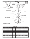
1. Unscrew the Y154-54-C and Y154-56-C screws from the
Y22-10-C nuts.
2. Lift the 29919 housing and nut assembly from the 29446 base.
3. Remove the 29273 spring cap and (B) spring. (For Model
27521-300, unscrew the Y154-54-C and Y154-56-C screws
from the 104135 cap. Also remove Y14-10-C lockwashers.)
4. The 29000 and 90860 diaphragms are now accessible. Unscrew
(D) seat assembly from the 29446 base. This provides access to
(D) seat assembly and 29449 seal and 29451 spring.
1. Place 29451 springin 29446.Set (F)ball ontop ofspring. Usenew
29449 seal, place it on 29446 base.
2. Screw (D) seat assembly into 29446 base and tighten to 20 ft. lbs.
3. To assemble diaphragm place 29000 and 90860 diaphragms toĆ
gether. Place 90860 diaphragm next to the hex over the threaded
end of the (E) pushrod.
4. Apply Loctite 242 to threads on (E) pushrod. Screw (E) pushrod
into (C) back-up plateand tighten,making sureall holesinthe diaĆ
phragms align. Align holes in diaphragms with holes in base.
5. Place 29919 housing and nut assembly on the 29000 diaphragm.
6. Insert Y154-54-C and Y154-54-C screws through the holes in
the 29919 housing and nut assembly.
7. Place Y22-10-C nuts on screws and tighten. (For Model
27521-300, assemble 104135 cap to 29446 base using
Y154-54-C and Y154-56-C screws. Also include Y14-10-C
Lockwashers.