


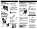
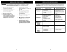

TROUBLESHOOTING
14
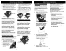
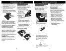
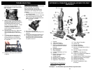
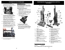
APPRENEZ À CONNAÎTRE VOTRE BALAYEUSE CYCLONIC
VERTICALE
Spécifications Techniques
Voltage : 120V, 60Hz.
Alimentation : 12 A
Remarque: * Les illustrations peuvent différer du produit exact.
35
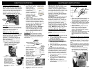
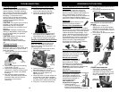
15. Tuyau Super Extensible
16. Suceur Plat
17. Brosse à Meubles
18. Brosse à Épousseter
19. Bouton de Dégagement du Bac à
Poussière
20. Port de Rinçage du Collecteur
Cyclone
21. Support du Tube Supérieur
22. Support de Dégagement Rapide du
Cordon d’Alimentation
23. Dégagement du Tube Télescopique
24. Support du Cordon d’Alimentation
25. Bouton Marche/Arrêt
26. Brosse pour Planchers
27. Brosse Puissante pour Poils
d’Animaux
1. Poignée
2. Tube Télescopique
3. Poignée de Transport
4. Bouton de Dégagement de la
Porte Inférieure du Collecteur
Cyclone.
5. Collecteur Cyclone
6. Bac à Poussière
7. Écran de Débris
8. Lumière d’Indicateur du Filtre
9. Lumière
10. Bouton d’Ajustement de la
Hauteur du Tapis
11. Protège-Meuble
12. Déclencheur de Poignée
13. Sélecteur Tapis-à-Plancher
14. Support du Tube Inférieur
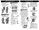
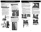
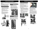
Changing the Headlight
WARNING: To reduce the risk of electric
shock, the power cord must be
disconnected before performing
maintenance/trouble shooting checks.
Occasionally the headlight will require
changing.
1. Turn the vacuum off and unplug from
the electrical outlet.
2. With a flathead screw driver, insert the
end of the screwdriver into the two
slots on top of the headlight lens and
gently pull down. (Fig. 55)
Fig. 55
Lens Slots
3. Lift out the headlight lens.
4. Remove the light bulb by pulling it out
carefully.
5. Replace the new bulb by pushing it in.
6. To replace the headlight lens, insert
the bottom tabs of the lens into the
holding slots and snap the top back
into place to secure.
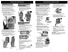
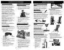
8. Once having removed the brush roll
completely, you will be able to easily
remove the belt from the motor driven
shaft. (Fig. 53)
9. Slide one end of the new belt over
the drive shaft, and the other end of
the belt around the brush roll. Secure
the left side of the brush roll into
place, and then the right side. Check
to make sure that the belt is
completely centered on the motor
driven shaft and that the brush roll
turns smoothly.
10. Replace the locking clip. Make sure
that the bottom part of the belt is
under the bottom part of the locking
clip.
11. To replace the belt and brush roll
cover, lineup the 4 locking tabs on
the belt and brush cover with the
slots on the power nozzle and push
in. (Fig. 54)
Fig. 53
12. Rotate the locking screws clockwise
to tighten.
Fig. 54