MDrive34 Motion Control Datasheet REV121704 2
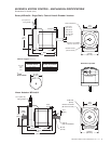
MDRIVE34 MOTION CONTROL SPECIFICATIONS
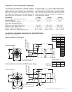
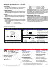
WIRE/PIN ASSIGNMENTS
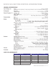
GENERAL SPEC I FI CA TIONS
Input Voltage (+V)
Range.....................................................................................+24 to +75 VDC
Power supply current requirements = 4 Amps (max) per MDrive34. Actual current depends on voltage and load.
Analog Input
Resolution .............................................................................................10 Bit
Voltage Range..............................................................0 to +5 VDC or 4-20 mA
General Purpose I/O
Number/Type ........................................................................ 4/Open Collector
Logic Range ..............................................................................+5 to +24 VDC
Output Sink Current .............................................................................700 mA
Protection ............................................ Over Temp, Short Circuit, Inductive Clamp
Communication
Type ...................................................................................................RS-485
Baud Rate.................................................................................4800 to 115K
Motion
Resolution – Open Loop Confi guration
# of Settings..........................................................................................14
Steps Per Rev....................
400, 800, 1000, 1600, 2000, 3200, 5000, 6400,
10000, 12800, 25000, 25600, 50000, 51200
Resolution – Closed Loop Confi guration (optional)
Steps Per Rev..................................................................................51200
Encoder (optional)
Type ................................................................................Internal, Mag net ic
Resolution ................................................... 512 Lines/2048 Edges Per Rev
Counters
Type .................................................................... Position, En cod er/32 Bits
Edge Rate (Max)................................................................................ 5MHz
Velocity
Range....................................................... +/- 5,000,000 Steps Per Second
Resolution ............................................................0.5961 Steps Per Second
Accel/Decel
Range.............................................................. 1.5 x 10
9
Steps Per Second
2
Resolution ...............................................................90.9 Steps Per Second
2
Software
Program and Data Storage................................................................Nonvolatile
User Registers.................................................................................. (4) 32 Bit
User Program Labels and Variables ...............................................................22
Math Functions ...............................+, -, ×, ÷, >, =, <, <=, >=, AND, OR, XOR, NOT
Branch Functions ....................................................... Branch & Call (conditional)
Predefi ned I/O Functions
Inputs .............................................. Home, Limit Plus, Limit Minus, Go, Stop,
Pause, Jog Plus, Jog Minus, Analog In
Outputs................................................... Moving, Fault, Stall, Velocity Change
Trip Functions ...................................................... Trip on Input & Trip on Position
Party Mode Addresses.................................................................................62
Encoder Functions ........................Stall Detection, Position Maintenance, Find Index
Thermal
Heat Sink Temperature (Max) ................................................................... 85° C
Motor Temperature (Max)...................................................................... 100° C
Protection
Protection .................................................................................... Over Voltage
CONNECTOR P1 – Flying Leads
WIRE COLOR FUNCTION
White/Yellow I/O 1
White/Orange I/O 2
White/Violet I/O 3
White/Blue I/O 4
Green ANALOG INPUT
Black POWER GROUND
Red +V (+24 TO +75 VDC)
CONNECTOR P2 (RS-485) – 10 Pin Pin-Header
PIN FUNCTION
1-5 NO CONNECT
6 RX +
7 RX –
8 TX –
9 TX +
10 GROUND


