


Copyright © Intelligent Motion Systems, Inc. www.imshome.com
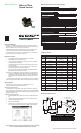
P1
P2
P2
P1
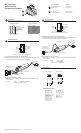
Connector Style Function
Pluggable Terminal......................
I/O and Power
Flying Leads................................ I/O and Power
10-pin IDC................................... Communications
10-pin Wire Crimp.......................
Communications
MDrive17Plus
Speed Control
Connectivity Options
P2
P2
I/O & Power
Pluggable terminal or flying leads
Encoder Options
External Optical (Differential or Single-End)
P1
User Supplied Recommended
Wire: 22 AWG Stranded
Stop/Start
CW/CCW Direction
+5 VDC Output
Speed Control
Logic Ground
GND
+V
Pluggable Terminal Flying Lead Colors
1
3
5
7
2
4
6
Wire Color Function
Violet Stop/Start
Blue CW/CCW Direction
Green Speed Control
Yellow +5 VDC Output
Gray Logic Ground
Black Ground
Red +V
Mating Connector Kit p/n: CK-01
Use to make your own cables, kit contains 5 mating connector shells for making
interface cables.
IDC Parts Shell: SAMTEC TCSD-05-01-N
Ribbon Cable: AMP 1-57051-9
Mating Connector Kit p/n: CK-02
Use to make your own cables, kit contains 5 mating connector shells for making
interface cables.
Hirose Parts Shell: DF11-10DS-2C
Pins: DF11-2428SC
Crimp Tool: DF11-TA2428HC
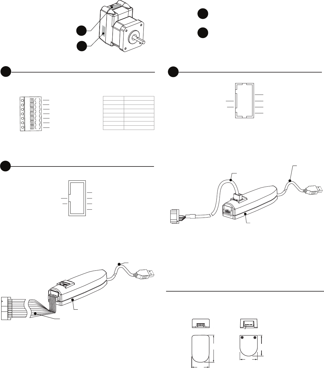
MISO
+5 VDC Out*
Chip Select
MOSI
SPI Clock
GND
1
3
5
7
9
2
4
6
8
10
pins not labeled are no connect.
*used to power the MD-CC300-001 only.
To computer
USB port
To MDrivePlus 10-pin
IDC connector
6.0’ (1.8m)
in-line converter
6.0’ (1.8m)
Communications Converter p/n: MD-CC300-001
Electrically isolated in-line USB to SPI converter pre-wired with mating connector
to conveniently program and set configuration parameters.
Communications Converter p/n: MD-CC302-001
Electrically isolated in-line USB to SPI converter pre-wired with mating connector
to conveniently program and set configuration parameters.
Communications
10-pin IDC
Communications
10-pin Wire Crimp
Single-End OpticalDifferential Optical
(Pin 1) Brown: Ground
Violet: IDX
Blue: CH A
Orange: +5 VDC In
Yellow: CH B
Orange/White: +5 VDC In
White/Orange: Ground
White/Blue: CH A-
Blue/White: CH A+
White/Green: CH B-
Green/White: CH B+
White/Brown: IDX-
Brown/White: IDX+
p/n: ED-CABLE-6
6.0’ (1.8 m)
p/n: ES-CABLE-2
12” (30.4 cm)
Optional Encoder Cables
wire color: function wire color: function
2.04
(51.8)
.
1.22
(31.0)
.
Pin 1
1.20
(30.4)
1.42
(36.1)
.
.
MISO
GND
SPI Clock
+5 VDC Out*
MOSI
Chip Select
9
7
5
3
1
10
8
6
4
2
pins not labeled are no connect.
*used to power the MD-CC302-001 only.
To computer
USB port
To MDrivePlus
10-pin friction lock
wire crimp connector
6.0’ (1.8m)
in-line converter
6.0’ (1.8m)