


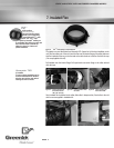

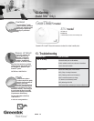
figure 11.3 Magnehelic Gauge at «0»
PAGE
11
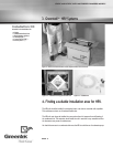
STATIC AND STATIC WITH MOTORIZED DAMPERS MODELS
Maximizing the
unit’s
performance
installation
The HRV must be balanced properly in
order to operate at maximum performance
and avoid problems.
Balancing the Unit
installation
Balancing the unit is an important step in
the installation of the HRV. The operation
consists of measuring and regulating the
volume of fresh air from outside passing
through the unit is equal with the exhaust
air from home.
A 10% variation is acceptable, in such case,
the volume of exhaust air from home
should be superior than the volume of fresh
air from outside.
Refer to Ventilation Needs, page 3 to
determine what is the volume of air needed
for your specific installation.
Before Starting
the Balancing
Operations
installation
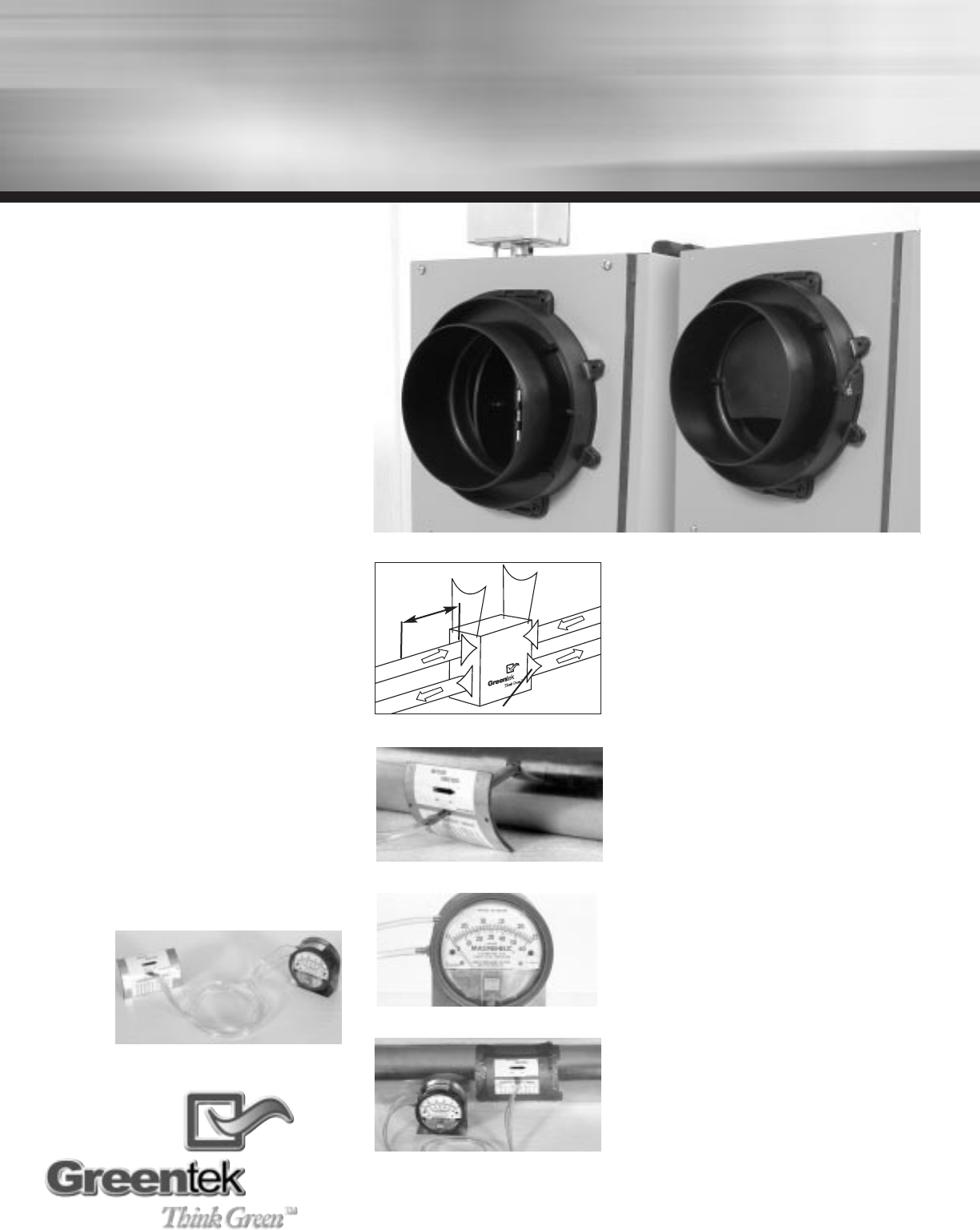
A Magnehelic gauge equiped with an air
flow grid is used to measure the volume of
air passing through the unit and ducting sys-
tem. Make sure that the airflow grid is the
same size as the conduit beeing mesured.
Check for size on grid. (Figure 11.6)
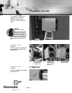
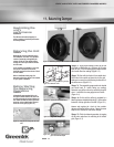
11. Balancing Damper
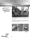
Step 1:
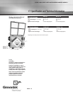
To get proper readings, mount the air flow
grid inside a rigid ducting at a minimum of 18 inches
from the unit. This will avoid getting unstable airflow
witch could offset the readings. (Figure 11.2)
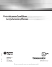
Step 2:
Start with the fresh air from outside duct.
Drill a hole in the conduit and insert the air flow grid.
Make sure to mount the grid following the direction of
the airflow arrow. (Figure 11.3)
Step 3:
The magnehelic gauge needs to be leveled
and should read «0» before taking any readings.
Determine your airflow volume by consulting the grid’s
chart. It can differ from one gauge size to an other.
(Figure 11.4)
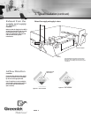
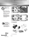
Step 4:
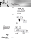
On this unit the airflow is regulated by a
balancing damper installed inside the ISF
TM
collar system
located on the top right side of the HRV. (Figure 11.1)
Measure and regulate the «fresh air from outside»
damper until desired airflow volume. Repeat the same
steps for the «exhaust air from home» damper.
Step 5:
Finish the balancing operation by tapping
all the holes made from the mounting of the airflow
grid. (Figure 11.5)
figure 11.1 Balancing Dampers- Model SHM
TM
and Model SH
TM
figure 11.6 Magnehelic Gauge with Air Flow
Grid
figure 11.2 Minimum of 18”
figure 11.3 Inserting Air flow grid in duct
figure 11.5 Avoid leakage by sealing air flow
grid in duct with duct tape.
18”
Balancing Dampers