


INSTALLATION
11
Concord CXSi/H - Installation & Servicing
6
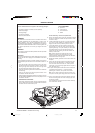
BOILER SECTION ASSEMBLY
The site assembled boiler is supplied in the following packages:
! Combustion chamber / manifold / burner assembly.
! Platework package.
! Casing package.
! Controls box package.
! End and centre sections.
TOOLS REQUIRED
! Spanners
! Torque wrench
! Pozi screwdriver
! Mallet
GENERAL
The installation of the boiler must be in accordance with current
Gas Safety (Installation and Use) Regulations or rules in force,
building regulations, I.E.E. (BS.7671) Regulations and the bye-
laws of the local water undertaking. It should also be in accordance
with the relevant British Standard Codes of Practice together with
any relevant requirements of the local gas supplier and local
authority.
ASSEMBLY
The combustion chamber should be positioned as near as possible
to the installation site.
IMPORTANT.
It must be remembered that the boiler distribution tube has to be
fitted into the rear return tapping of the assembled boiler before
final siting.
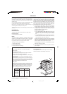
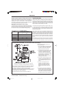
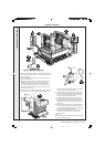
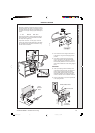
Prior to assembling the sections it will be necessary to remove the
manifold assembly and burners from the combustion chamber. To
do this:
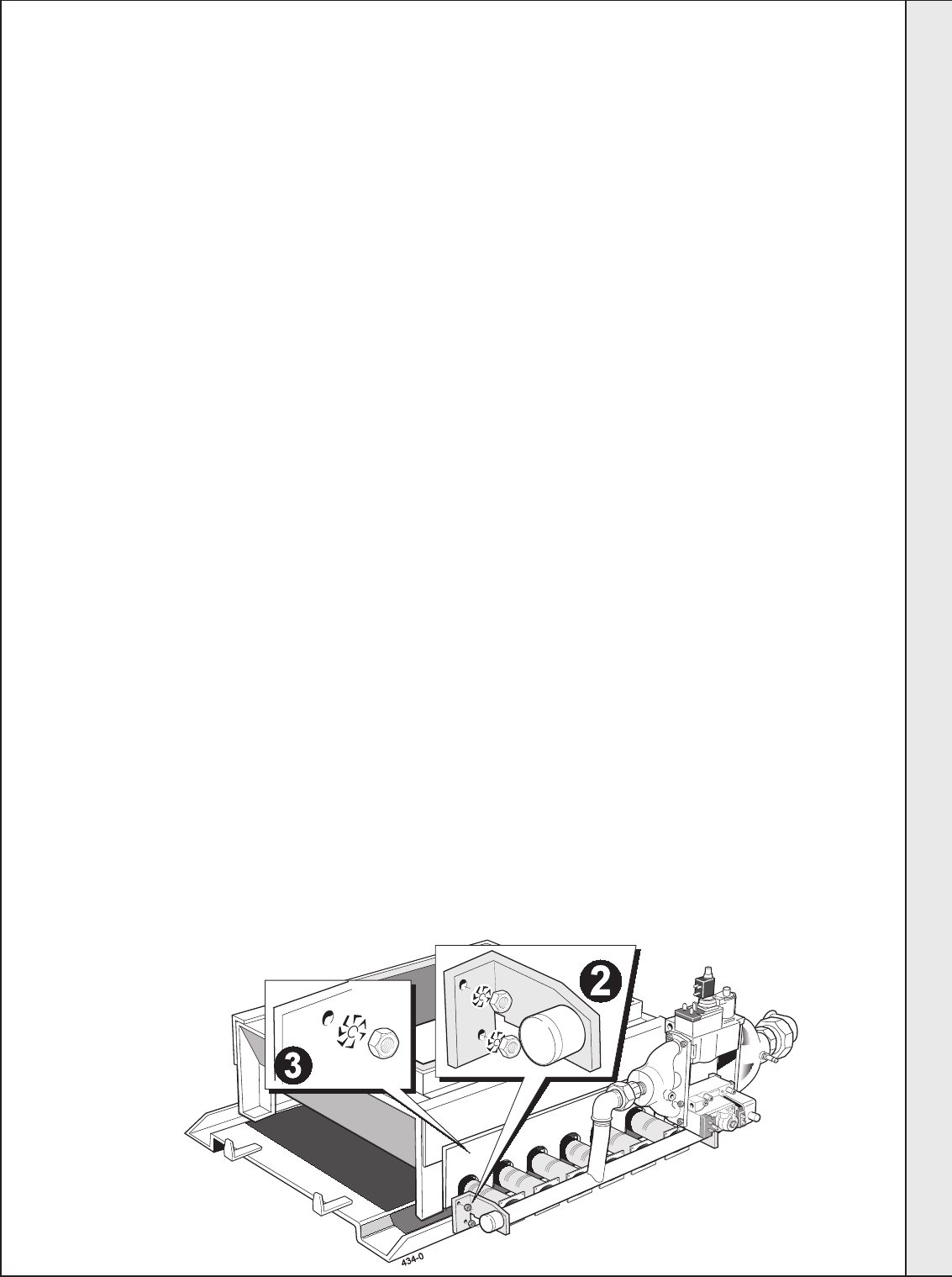
1. Undo the two M5 screws and washers securing the spark
generator bracket to the combustion chamber. Undo the union
securing the gas valve assembly and remove the gas valve
and spark generator assembly from the boiler.
2. Undo the 4 nuts securing the burner manifold to the combustion
chamber legs.
3. Undo the nuts securing the burner light back shield to the
combustion chamber and lift it off.
4. Pull the whole burner assembly forward on its runners, ensuring
that no wires are trapped, and remove it completely from the
combustion chamber.
PREPARATION OF SECTIONS
Each section should be brushed clean on all external surfaces
and any debris which may have accumulated within the sections
should be removed via the bottom ports.
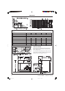
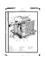
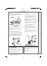
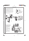
Section Assembly - refer to the exploded view
5. Take an end section and lift it onto the combustion chamber
so that the combustion chamber side panel return is inside
the section rear lip.
6. Locate a slotted steel ring and an ‘O' ring seal into each of
the 4 ports. It will be necessary to squeeze the steel ring
slightly to enable it to be pushed fully into the recess.
7. Lift a middle section onto the combustion chamber and
carefully offer it up to the end section until it engages the
projecting steel rings. It may be necessary to use a mallet
and hardwood block to ensure that the steel rings are
pushed fully into the recessing and that the sections are
butted up to each other.
Note. Until the final section is fitted and the tie rods
fastened, the sections in the assembly are not fixed
together therefore CARE MUST BE TAKEN TO PREVENT
the installed sections coming apart.
8. Repeat the assembly procedure for all of the sections until
complete.
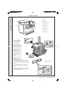
9. Fit the 4 tie rods through the holes in the sides of the end
sections and fit a flat steel washer, a shakeproof washer
and a nut to both ends of each tie rod. Screw up all the
nuts equally, in turn and, finally, tighten them to a torque of
38-41 Nm (28-30 lb. ft).
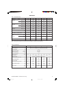
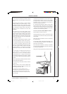
10.For open vented systems a site test must be carried out at
a hydraulic pressure equal to 1
1/2 times the design
pressure given in Table 2, for a period of 30 minutes.
Note. If it is a sealed system the hydraulic pressure must
be equal to twice the given design pressure for 30 minutes.
11. Fit the 4 coach bolts into the lugs at the bottom of the end
sections and through the hole in the retaining angle of the
combustion chamber.
Fit a flat washer and nut and secure the section assembly
to the combustion chamber.
INSTALLATION
157294-3.pmd 11/8/2005, 9:58 AM11