


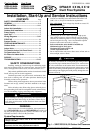

5
CAUTION
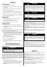
REASSEMBLE
1. Connect the display connector to the display panel printed
circuit board.
2. Put the control box cover and grille frame back on using the
appropriate screws (Steps 3 and 4 of Wire the Indoor Unit
section). Put the grille insert back on.
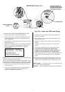
MAKE DRAINAGE CONNECTIONS
1. Connect the unattached end of the drainage tube to the
drainage hose outlet.
2. Seal the drainage connection to prevent leakage.
3. Make sure there are no kinks, "U" bends or flattened sections
in the tube.
4. Check that the drainage functions properly. Fill the pan below
the unit's coil with water and observe that it freely drains out.
5. Make sure the drainage hose is at the bottom side of the wall
through-hole (see Fig. 5).
FILTER
IR
RECEIVER
POWER/AIRCOND
TIMER
FUSE
AUTO/OFF
FILTER RESET
SERVICE LED
POWER/AIRCOND
TIMER
FUSE
AUTO/OFF
FILTER RESET
SERVICE LED
AUTO/OFF
FILTER RESET
SERVICE LED
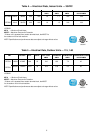
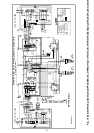
HEAT PUMP
Model-2 X12 DIP Switches location
(on the Control Box side)
HEAT PUMP
Models-2 X 09 DIP Switches location
(on the Control Box side)
COOLING ONLY
Model-2 X12 DIP Switches location
(on the Control Box side)
COOLING ONLY
Models-2 X09 DIP Switches location
(on the Control Box side)
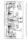
Standard Dip Switches
status from the factory
Inter unit
terminal block
30VDC
Display
Connection
TH1
TH2
TH3
(Heat Pump Only)
Inter unit cable clamp
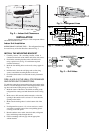
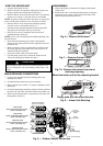
WIRE THE INDOOR UNIT
1. Strip the cables back 1/4 inch.
2. Remove the unit's front panel by lifting the lower part and
pulling it gently outward and upward. See Fig. 6.
3. Remove the two screws from the control box cover and take
off the cover. See Fig. 7. Save the screws to reassemble.
NOTE: In general wiring the indoor unit does not require the
removal of the grille frame but in case of need do as follow:
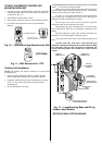
4. Remove the two screws from the air discharge opening.
Save the screws to reassemble. See Fig. 7A.
•
Pull downwards and outwardston the bottom of the grille
and gently raise the frame of the top of the unit.
•
Once all covers are off, mount the unit onto the wall
mounting bracket. See Fig. 8 .
NOTE: Leave covers off until after the Making Drainage Con-
nections section.
•
Route the interconnecting unit's electric cable and the
outdoor sensor cable towards the lower right hand corner of
the indoor unit.
•
Make sure that the wires are connected in accordance with
the wiring diagram on the inside of the unit front cover or
within this instruction manual.
•
Secure the control cables to the strain relief.
•
For heat pump systems only, connect the outdoor sensor
TH3 to its mating black terminal. See Fig. 9.
Make sure that all wires and screws are firmly fastened. Loose
wires or connections can cause damage and present a fire
hazard.
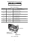
Fig. 6 — Remove Grille Insert
Fig. 7 — Remove Control Cover
Fig. 8 — Indoor Unit Mounting
Mount the indoor unit on the mounting bracket
Gently push with the arrow direction
Fig. 7A - Remove the screws from the air
discharge opening.
Fig. 9 — Outdoor Sensor Connection
1
2