


Copyright 2007 - Morse Mfg. Co., Inc. Form PL400-60 (0604-____) (Updated 10/2007) Page 5
Assembly Instructions for Morse Hydra-Lift Drum Karrier Model 400A-60
Serial Number 0604 to ____ (MMYY)
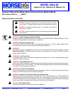
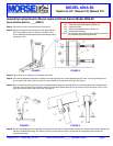
Step #1: Place tower on floor, push-handle down. See figure 1.
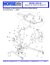
Step #2: Attach each leg (item 4) using two 3/8-16x3” grade 5 bolts
(item 2), flat washers (item 3), and lock nuts (item 13) as
shown. Wheels should be parallel when assembled properly.
See figures 1 & 2.
Step #6: Remove sealing plug from the top of hydraulic reservoir and fill reservoir with included container of hydraulic fluid. Replace sealing plug
with the included breather plug. Your Hydra-Lift Karrier is now ready for service. Please refer to the operating and maintenance
instructions provided.
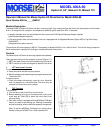
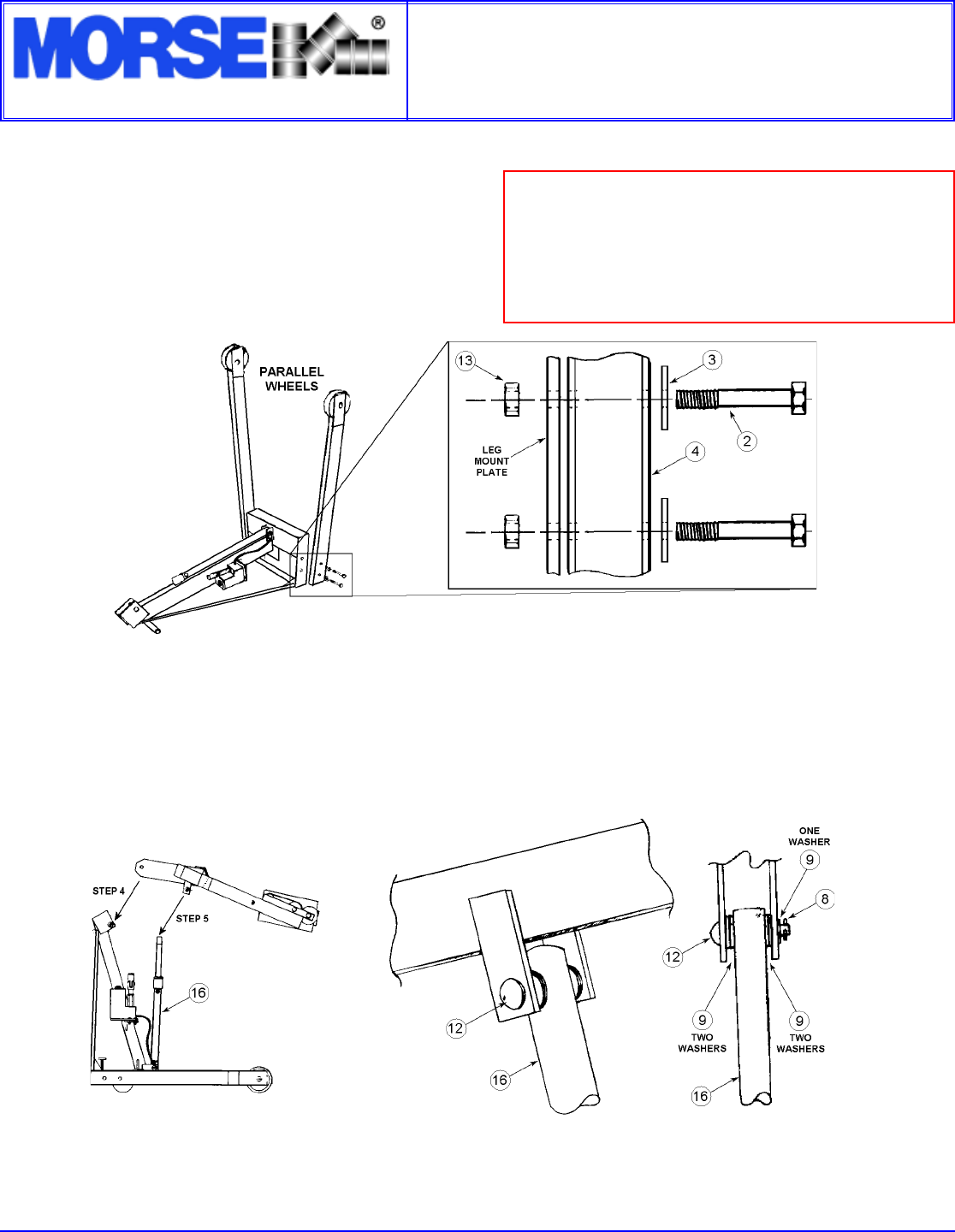
Step #3: Tip the tower up so it stands on the casters and wheels.
Step #4: Lift overhead assembly into position. A drift pin can help align the holes. Insert a greased clevis pin (item 12) through mast cap and
boom. Install a 5/8” washer (item 9) and 3/16” roll pin (item 8) in the end of the clevis pin. See figure 3.
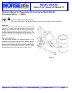
Step #5: Next, connect the cylinder (item 16) to the overhead assembly: Align ram eye with holes in boom clevis plates and insert a greased
clevis pin (item 12) with four 5/8” washers (item 9). Place another washer (item 9) on outer end of clevis pin and drive a 3/16” roll pin
(item 8) into the hole at the end of clevis pin. See figure 4.
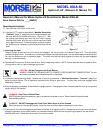
Please unpack and identify the following parts:
1 ea. Tower with hydraulic pump and cylinder, etc.
2 ea. Legs with wheels
1 ea. Overhead assembly with drum holder, etc.
1 ea. Package with hardware
NOTE: The clevis pins and mating surfaces at their joints should
be coated with grease during assembly.
FIGURE 4FIGURE 3
FIGURE 1
FIGURE 2
The Specialist In Drum Handling Equipment
MODEL 400A-60
Hydra-Lift, 60”, Manual Lift, Manual Tilt