


12
41753-01 • 02/17/10 • Hunter Fan Company
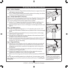
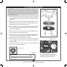
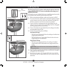
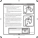
7-1. Align the holes on the gasket and stick two screws through two of the
holes.
7-2. read the plug connector from the mounting plate through the
gasket. Partially install the gasket to the mounting plate with the two
screws.
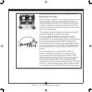
7-3. Place the upper switch housing over the two screws and turn
counterclockwise so that the screws t securely in the slots.
7-4. Partially install the third screw and then tighten all three screws
securely.
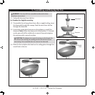
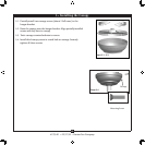
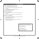
7-5. Connect the upper plug connector from the motor to the lower plug
connector in the switch housing assembly.
Note: Both plug connectors are polarized and will only t together
one way. Make sure the connectors are properly aligned before
connecting them. Incorrect connection could cause improper
operation and damage to the product.
7-6. To attach the lower switch housing,
align the side screw holes in the
upper and lower switch housings. Attach the lower switch housing
to the upper switch housing with three housing assembly screws.
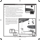
Note: You can customize your Hunter fan with a number of accessory light
kits.
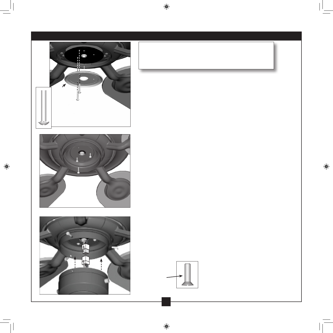
Housing
Assembly
Screw
Steps 7-1 – 7-2
Step 7-4
Gasket
Note: If you are installing a light xture, do NOT install the
switch housing without rst referring to the instructions
included with the light xture.
Steps 7-5 – 7-6
7 • Completing Your Installation