


[5]
44806 04/02/2008
[a]
[a]
[a]
[a]
[b]
[b]
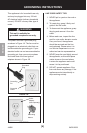
ASSEMBLY
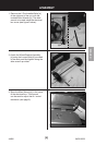
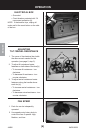
3. Store the Allen Wrench [a] in the cover
of the electrical box. This wrench
can be used to adjust the tilt / swivel
resistance (see page 6).
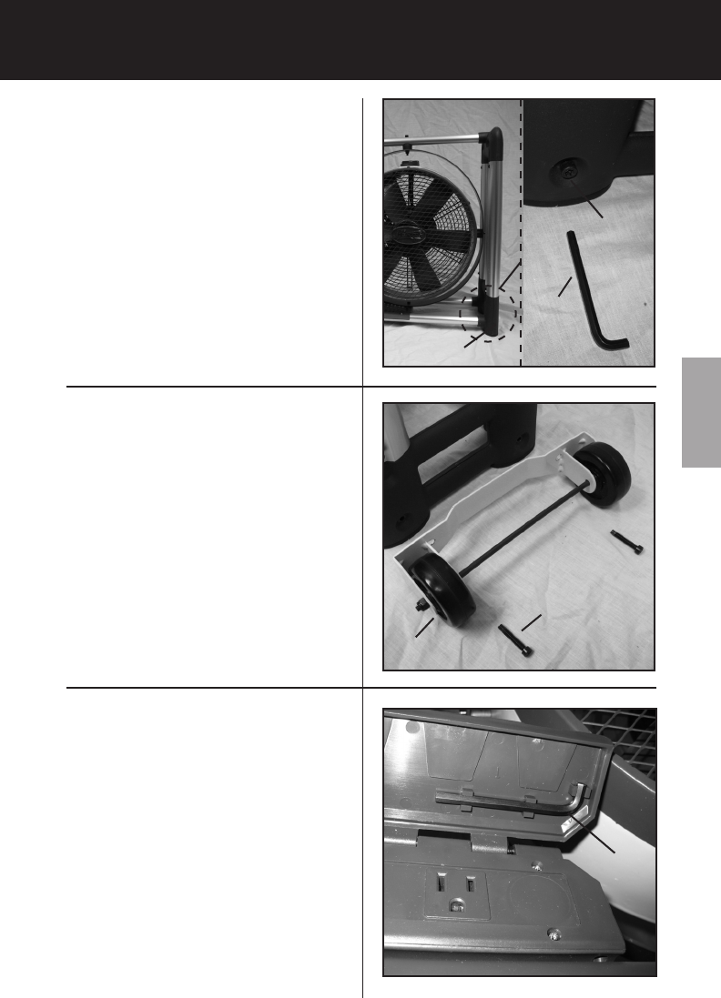
1. Remove the 2 Pre-Installed Bolts [a]
of the right end of the unit, with the
included Allen Wrench [b]. The allen
wrench is located inside the electrical
box cover (see gure 3 below).
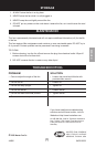
2. Attach the Wheel Bracket Assembly
[a] using the Longer Bolts [b] provided
in the sack parts and tighten using the
allen wrench provided.
ENGLISH