41746-01 05/02/2005 7
ENGLISH
21. Align the keyhole slots in the
back grille with the three screws
re main ing in the motor face and
place the back grill onto the
screws with the washers in front
of the grille, next to the head of
the screw.
22. Rotate the back grille clockwise
to situate the screws in the nar-
row ends of the keyhole slots.
23. Install the fourth screw into the
remaining hole and tighten all
screws.
24. Place the blade assembly over
the motor shaft lining up the
blade as sem bly setscrew on the
back of the blade shaft with the
rectangular indentation in the
motor shaft. Rotate the motor
shaft as needed.
25. Tighten the blade setscrew so
that it sits in the rectangular in-
den ta tion, preventing the blades
from touching the back grille
or coming off the shaft. Gently
pull the blades back and forth
to check if the setscrew is in the
right place.
26. With the Hunter logo facing
forward, engage the tabs in the
lower part of the front grille into
the rim of the back grille.
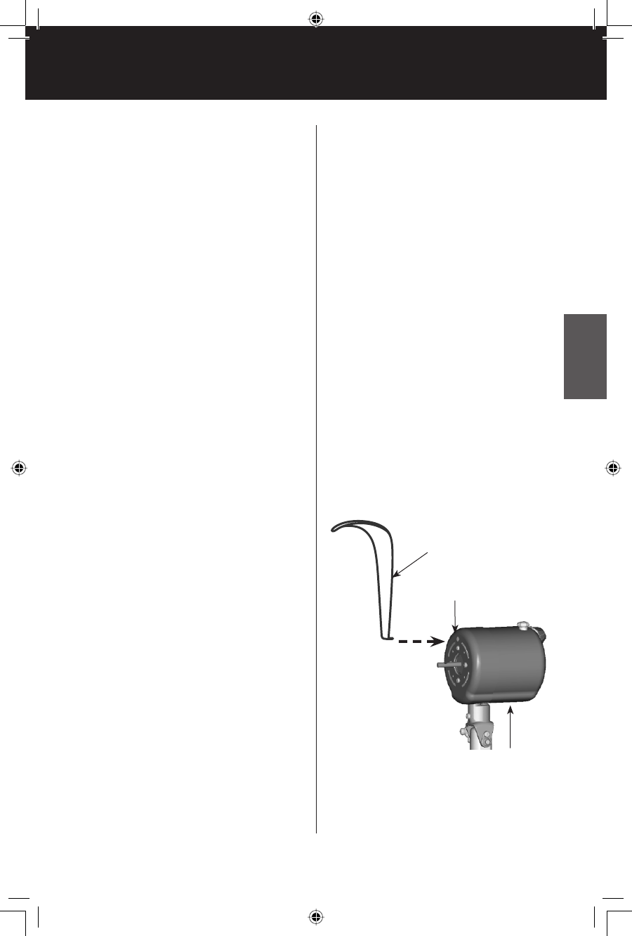
27. Insert the interlock switch into
the hole on the top of the mo-
tor face. See Figure 6.
28. Place the bracket on the inter-
lock switch over the back and
front grille, aligning the holes in
the bracket with the holes in the
tab on top of the front grille.
Install the two grille assembly
screws.
29. Place the grille ring over the
two grille rims leaving the open-
ing at the bottom and the ring
screw on the back side of the
fan.
30. Latch the two sides of the
ring together and secure with
the ring screw. The ring screw
should be installed through the
thin side of the ring tabs to the
thick side of the ring tabs.
FIGURE 6
Interlock Switch
Hole in motor face
Fan
Motor
41746_CentFan_04.29.05.indd 7 5/2/05, 10:51:02 AM


