


3
®
RH
G
R
C
Y/O
Y1
W/B
x
RH
x
RC
x
G
x
Y/O
x
W/B
x
Y1
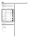
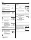
RH, R, VR or 4
24 Volt
RC, VC
24 Volt Cool
G or F
Fan
Y, C or M
Air Conditioning Compressor
- or -
O
Reversing Valve operating in Cool mode.
(Single Stage Heat Pumps ONLY.)
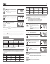
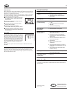
If the code letter on your
existing thermostat is
then mark the wire
with label shown
and connect to thermostat
terminal shown
W or H
Heating
- or -
B
Reversing Valve operating in Heat mode.
(Single Stage Heat Pumps ONLY.)
Y1
Heat Pump compressor
(Single Stage Heat
Pumps ONLY.)
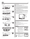
Wire Labeling (Continued)
■ After labeling wires, disconnect them from the existing thermostat terminals.
■ Remove existing wallplate. To make sure wires do not fall back into wall opening, you may
want to tape them to the wall.
■ If hole in wall is larger than necessary for wires, seal this hole with insulating material so that
no hot or cold air can enter the back of the thermostat from the wall. This air could cause a
false thermostat reading.
Table A
NOTE: Do not connect a “Common” wire (sometimes labeled “C”) to any terminal on
this thermostat. Tape up the wire and do not use. This wire provides electricity to non-
battery powered thermostats.
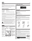
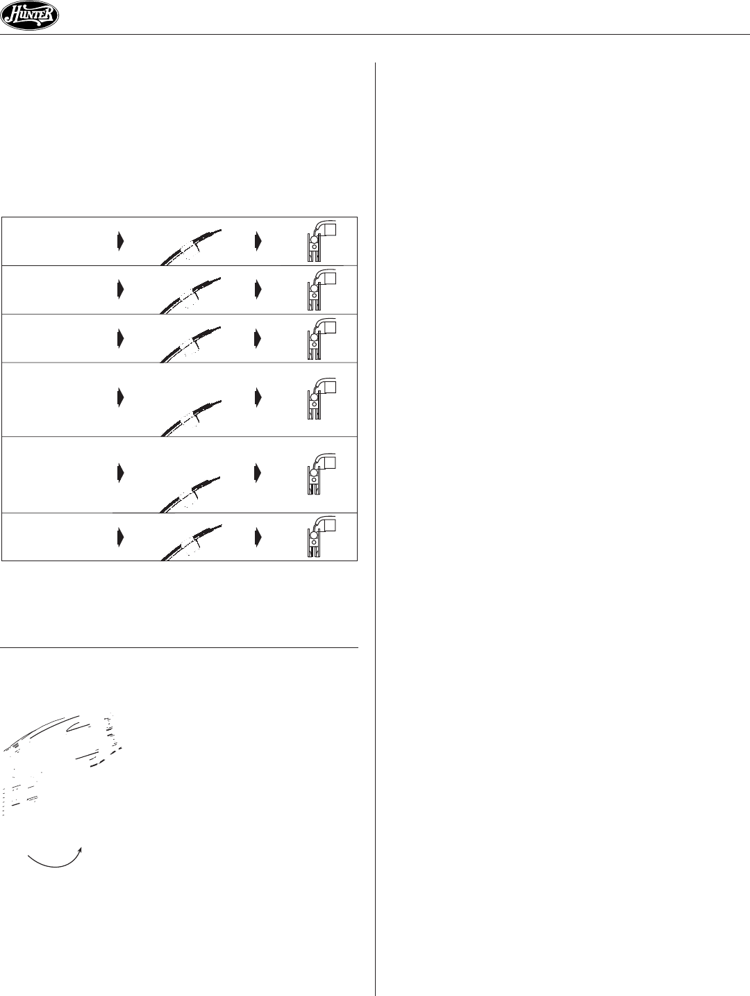
Mount Wallplate and Thermostat
■ Remove the wallplate from your thermostat by pressing the release tab on the bottom of the
thermostat. See Figure 2.