


Fan Co.
7130 Goodlett Farms Pkwy,
Suite 400
MEMPHIS, TN 38016
© 2009 Hunter Fan Company
Form No. 44004-01 R030409
Wall-Mount
Indent
Figure 9.
1. Replace the Outer Cover as shown in
Figure 10. Use the four screws to secure
the Outer Cover.
2. Rest the Remote sensor on the
horizontal surface of your choice.
Figure 10.
Ch
TEMP
Ch
TEMP
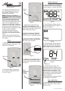
If your Remote Sensor is set to show
the temperature in Celsius, the display
will show the ºC indication next to the
temperature. See Figure 11.
Ch
T E M P
C
Figure 11
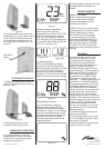
Temperature Measurement Range
Your Remote Sensor will show
temperatures from -40ºF to 122ºF (-40ºC
to 50ºC). If the temperature is greater
than 122ºF (50ºC), the LCD will show
“HI”. See Figure 12A. If the temperature
is lower than -40ºF (-40ºC), the LCD will
show “LO”. See Figure 12B.
Figure 12A
Figure 12B
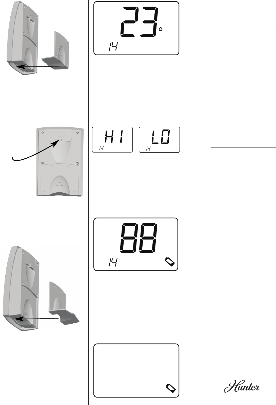
Low Battery Indication
When your Remote Sensor’s battery
is running low, the LCD will show the
ashing Low Battery Indication to remind
you to install two fresh AA Alkaline
batteries at your earliest convenience.
See Figure 13. At this point your Remote
Sensor will continue to function normally.
Figure 13.
Ch
T E M P
Depleted Battery Indication
If your Remote Sensor’s battery is
depleted to the point that the LCD is
showing only the ashing Low Battery
Indication, as in Figure 14, your Remote
Sensor has ceased functioning and will
continue in this condition until two fresh
AA Alkaline batteries are installed.
Without further attention, the LCD will
eventually go blank.
Your Remote Sensor will return to normal
operation when fresh batteries are
installed.
Figure 14.
Problem: LCD is Blank.
Solution: Make certain your Remote
Sensor’s batteries are 1) installed
correctly, with polarities correctly
positioned, and 2) fresh.
Problem: Thermostat is not showing the
same temperature as the Remote Sensor.
Solution: Make certain you have
the correct Remote Sensor selected
at your thermostat (if you are using
more than one Remote Sensor). If you
require further assistance, call Hunter
Fan Technical Support at 1-888-830-
1326 from 7am to 7pm Central Time
Monday thru Friday and 8am to 5pm on
Saturday.
to Stand on a Surface
teMperature IndIcatIon
This device complies with Part 15 of
the FCC Rules. Operation is subject
to the following two conditions: (1)
this device may not cause harmful
interference, and (2) this device must
accept any interference received,
including interference that may cause
undesired operation. This equipment has
been tested and found to comply with
the limits for a Class B digital device,
pursuant to Part 15 of the FCC Rules.
These limits are designed to provide
reasonable protection against harmful
interference in a residential installation.
This equipment generates, uses and can
radiate radio frequency energy and, if
not installed and used in accordance
with the instructions, may cause harmful
interference to radio communications.
However, there is no guarantee that
interference will not occur in a particular
installation. If this equipment does cause
harmful interference to radio or television
reception, which can be determined
by turning the equipment off and on,
the user is encouraged to try to correct
the interference by one or more of the
following measures:
• Increase the separation between the
equipment and receiver.
• Connect the equipment into an outlet
on a circuit different from that to which
the receiver is connected.
• Consult the dealer or an experienced
radio/TV technician for help.
Figure 8.
2. Use the provided screw to mount the
Remote Sensor on a wall or other vertical
surface. The back of the Remote Sensor
has a Wall-Mount Indent from which it
will hang from the provided screw. See
Figure 9.
troubleShootIng
technIcal