


8
45025-01 • 11/19/08 • Hunter Fan Company
All wiring must be in accordance with national and local electrical
codes and ANSI/NFPA 70. If you are unfamiliar with wiring, use a
qualified electrician.
Wall switches are not included. Select an acceptable general-use switch
in accordance with national and local electrical codes.
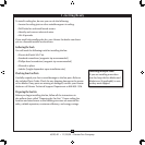
4-1. Before attempting installation, make sure the power is still o.
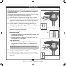
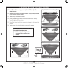
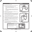
4-2. To connect the wires, hold the bare metal leads together and place
a wire connector over them, then twist clockwise until tight. For
all these connections use the wire connectors provided.
4-3. Connect the bare or green ground wire (grounded) from the
ceiling to the green ground wire (grounded) from the ceiling plate
and the green ground wire from the fan.
4-4. Connect the white wire (ungrounded) from the ceiling to the
white wire (ungrounded) from the fan.
4-5. Connect the remaining wires as follows:
Dual Switch Wiring:
• e black wire (ungrounded) from the ceiling to the black wire
(ungrounded) from the fan
• e black/white wire (ungrounded) from the fan to the wire
(ungrounded) for the wall switch
Single Switch Wiring:
• e black wire (ungrounded) from the ceiling to the black
(ungrounded) and the black/white wire (ungrounded) from
the fan
CAUTION: Be sure no bare wire or wire strands are visible after
making connections.
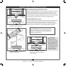
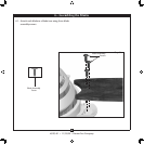
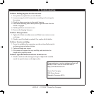
4-6. Turn the wire connectors upward and push them carefully back
through the ceiling plate into the outlet box.
4-7. Spread the wires apart, with the grounded wires on one side of
the outlet box and the ungrounded wires on the other side of the
outlet box.
Wire
Connector
4 •Wiring the Fan