


11
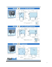
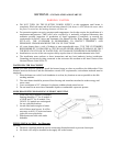
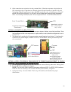
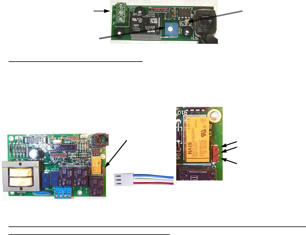
4. Make connections as required to the relay terminal block. When the temperature drops below the
XB1 setpoint the relay is open between Normally Open (NO) and Common (C) and the LED will
flash green. When the temperature is above the XB1 setpoint the relay is closed between NO and C
and the LED will be solid green. Use NO and C for low temperature interlock or high temperature
alarm. Use Normally Closed (NC) and C for low temperature alarm. A red LED indicates an error.
Relay Terminal Block LED
Temperature Adjustment
Potentiometer
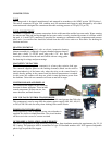
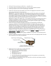
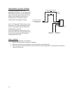
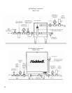
OPTIONAL REMOTE ALARM CONTACTS
1. If desired, the control board can be wired to a remote alarm to indicate a reset fault condition. These
fault conditions include over-temperature, no probe, and low water (when the configuration is set to
manual reset).
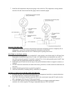
2. This alarm can be wired to the J4 connector on the control board as shown below. To facilitate this
installation, an optional adapter, Hubbell P/N PLUG ADAPTER J4, can be purchased to provide
wire connections.
J4 Connector Common
(NO)
(NC)
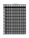
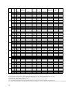
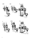
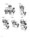
OPTIONAL FIELD CONVERSION FROM SINGLE TO THREE PHASE OR THREE TO SINGLE
PHASE (6, 7, and 9 kW models in 208 and 240 volts only)
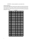
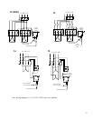
1. Find the appropriate diagram for the unit to be converted in the following chart titled “Wiring Chart”.
2. Re-wire the unit according to the diagram.
NOTE: The wire to be used for internal wiring must conform to SEW-2 or PTFE (200°C) and must
match the wire size currently in use. Contact the factory for assistance, if required.
3. Contact the factory for correct labels. The factory will need the serial number for proper
identification.
Note: Rating (resistive)
Max. Switching Power:
60W, 62.5VA
Max. Switching Voltage:
220VDC, 250VAC
Max. Switching Current: 2A
Max. Carrying Current: 3A
PLUG ADAPTER J4
Note: Rating (resistive):
Max.: 5A @ 120VAC
5A @ 24VDC