


THE ROUND® CREATIVE SERIES Y460A2003 THERMOSTAT
3 69-1358
❑
Firmly tighten the screws.
❑
Push the excess wire back into the wall.
❑
Plug the hole with nonflammable insulation to
prevent drafts from affecting the thermostat
operation.
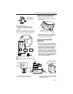
Y460A for heating/cooling system using separate RC-
RH terminals. If old thermostat has single R terminal,
refer to jumper drawing in Subbase Wiring procedure.
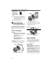
6 MOUNT YOUR THERMOSTAT
❑
Set the heat anticipator indicator to 1.2 before
mounting to prevent the anticipator from burning out
during installation.
❑
Align the thermostat over the subbase and tighten
the three captive mounting screws (see Step 4).
These captive mounting screws complete the
electrical connections to the thermostat.
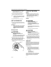
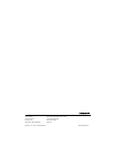
7 SET HEAT ANTICIPATOR
INDICATOR
❑
Be sure the thermostat adjustable heat anticipator is
set correctly to accurately control the temperature.
An incorrect setting (if too high) can result in wide
room temperature swings or (if too low) burn out the
anticipator, which voids the thermostat warranty.
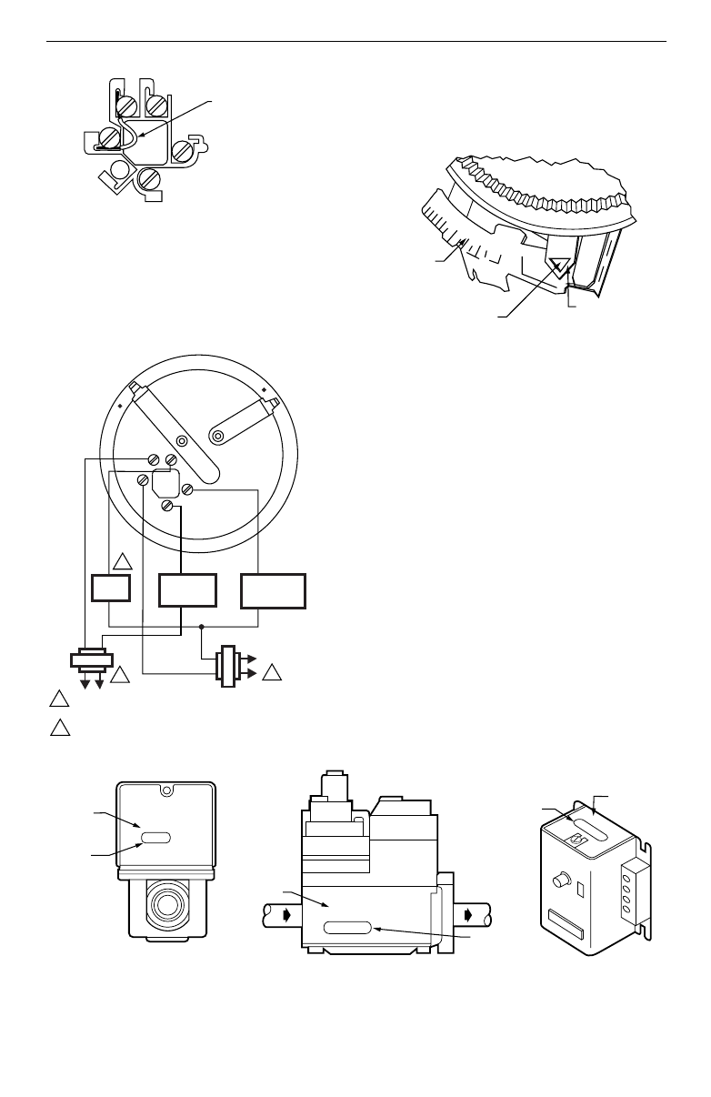
❑
Make sure you have the current draw (anticipator
setting) for your system. This is the number you
wrote in the box in Step 3. If you were unable to find
the current draw for Step 3, this information can be
found printed on the primary control at the furnace or
boiler. The primary control is usually a gas valve, a
relay or burner control box, Aquastat® Controller or
zone valve with the thermostat wires connected to it.
These controls are usually located behind the
furnace cover; see the illustration.
❑
If the current rating is still unavailable:
— Remove the W wire from the subbase.
— Connect one probe of an ac ammeter (0 to 2.0A,
for example) to the W wire and connect the other
probe to the W terminal.
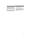
R
G
R
W
Y
EXAMPLE: FOR R
C
TO R
H
JUMPER, STRIP WIRE
END LONG ENOUGH TO
JOIN BOTH TERMINALS.
M1277A
H
C
M13418
2
POWER SUPPLY. PROVIDE DISCONNECT MEANS AND OVERLOAD
PROTECTION AS REQUIRED.
IN HEATING, THE FAN IS CONTROLLED BY ANOTHER CONTROLLER,
SUCH AS A HONEYWELL L4064 FAN AND LIMIT CONTROLLER OR
FAN TIMER.
1
1
1
COOL
HEAT
O
F
F
FAN
ON
AUTO
G
R
R
H
Y
W
C
HEATING
RELAY OR
VALVE COIL
COOLING
CONTACTOR
COIL
FAN
RELAY
2
LONGER
.15
.12
.2
.6
.8
1.0
.5
.4
.3
HOLE SUITABLE FOR
PENCIL POINT
TO MOVE INDICATOR
HEAT
ANTICIPATOR
INDICATOR
SCALE
M1368
V8043E 1004 4
24V 50/60CY
.32 AMP
@ 60CY
8406
24 Vac 50/60 Hz
0.4 AMP
30 VAC
0
.2
A
M
P
T
F
T
F
OIL BURNER CONTROL
SHOWS
CURRENT
DRAW
SHOWS
VOLTAGE
RATING
M6116B
FROM MAIN
FUEL SUPPLY
SHOWS
VOLTAGE
RATING
TO
BURNER
SHOWS
ANTICIPATOR
SETTING
TYPICAL GAS VALVE
ZONE VALVE
SHOWS
VOLTAGE
RATING
SHOWS
ANTICIPATOR
SETTING