


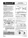
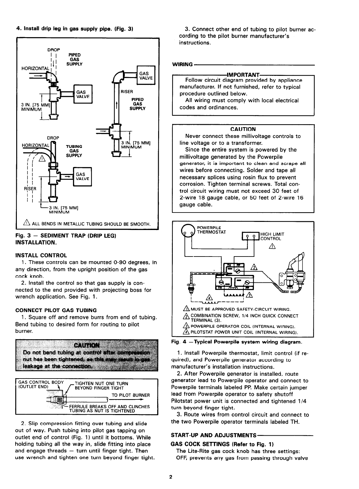
4. Install drip leg in gas supply pipe. (Fig. 31
DROP
I I
PIPED
DROP
PIPED
t
GAS
SUPPLY
A ALL BENDS IN METALLIC TUBING SHOULD BE SMOOTH.
Fig. 3 - SEDIMENT TRAP (DRIP LEG)
INSTALLATION.
INSTALL CONTROL
1. These controls can be mounted O-90 degrees, in
any direction, from the upright position of the gas
cock knob.
2. Install the control so that gas supply is con-
nected to the end provided with projecting boss for
wrench application. See Fig. 1.
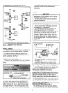
CONNECT PILOT GAS TUBING
1. Square off and remove burrs from end of tubing.
Bend tubing to desired form for routing to pilot
burner.
GAS CONTROL BODY
TIGHTEN NUT ONE TURN
BEYOND FINGER TIGHT
TO PILOT BURNER
t
FERRULE BREAKS OFF AND CLINCHES
TUBING AS NUT IS TIGHTENED
2. Slip compression fitting over tubing and slide
out of way. Push tubing into pilot gas tapping on
outlet end of control (Fig. 1) until it bottoms. While
holding tubing all the way in, slide fitting into place
and engage threads - turn until finger tight. Then
use wrench and tighten one turn beyond finger tight.
3. Connect other end of tubing to pilot burner ac-
cording to the pilot burner manufacturer’s
instructions.
WIRING
CAUTION
Never connect these millivoltage controls to
line voltage or to a transformer.
Since the entire system is powered by the
millivoltage generated by the Powerpile
generator, it is important to clean and scrape all
wires before connecting. Solder and tape all
necessary splices using rosin flux to prevent
corrosion. Tighten terminal screws. Total con-
trol circuit wiring must not exceed 30 feet of
2-wire 18 gauge cable, or 50 feet of 2-wire 16
gauge cable.
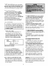
In POWERPILE
y A
-W
L-
-k****r-----
A MUST BE APPROVED SAFETY-CIRCUIT WIRING.
A COMBINATION scREw, 114 INCH 0uicK CONNECT
TERMINAL (3).
POWERPILE OPERATOR COIL (INTERNAL WIRING).
PILOTSTAT POWER UNIT COIL (INTERNAL WIRING).
Fig. 4 -Typical Powerpile system wiring diagram.
1. Install Powerpile thermostat, limit control (if re-
quired), and Powerpile generator according to
manufacturer’s installation instructions.
2. After Powerpile generator is installed, route
generator lead to Powerpile operator and connect to
Powerpile terminals labeled PP. Make certain jumper
lead from Powerpile operator to safety shutoff
Pilotstat power unit is connected and tightened l/4
turn beyond finger tight.
3. Route wires from control circuit and connect to
the two Powerpile operator terminals labeled TH.
START-UP AND ADJUSTMENTS
GAS COCK SETTINGS (Refer to Fig. I)
The Lite-Rite gas cock knob has three settings:
OFF, prevents any gas from passing through valve
2