


3
4
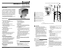
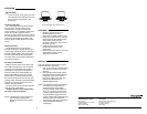
MOUNTING
The valve can be mounted in any position
on a vertical line. See Fig. 2. If the valve is
mounted horizontally; the actuator must be
even with or above the center line of the
piping. Make sure to leave enough room
above the actuator to remove the cover for
servicing.
Mount the valve directly in the tube or pipe
after the coil.
Make sure that the flow
through the valve is in the direction
indicated by the arrow stamped on the
valve body.
Sweat Copper Models
1. Use new, properly reamed pipe, free
from dents or corrosion.
2. Place the valve on the pipe. Set the
manual opening lever to MAN. OPEN
position before applying heat. This
protects the plug inside the valve by
removing it from the seat.
3. Sweat the joints, keeping the outer
surface free from solder. DO NOT use
silver solder because of the high
melting temperature required.
TO INSTALL A COMPLETE VALVE (V8043):
1. Disconnect power supply before
connecting wiring to prevent electrical
shock or equipment damage.
2. Install valve into pipe on the return side
of the coil. (See Mounting Section.)
3. Make wiring connections to valve. (Refer
to Wiring section for proper instructions.)
4. Inspect the valve installation to ensure
that all connections and adjustments
have been correctly made. Adjust the
M10162
VERTICAL
PIPING
HORIZONTIAL
PIPING
Fig. 2 - Mounting Positions
thermostat or controller connected to the
valve so that the valve runs through its
cycle. Make sure the valve runs
smoothly and positively from closed to
open to closed again. (See Operation
and Checkout Sections.)
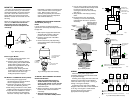
TO REMOVE THE ACTUATOR FROM THE
VALVE BODY (See Fig. 3)
NOTE!
It is not necessary to drain the hydronic
system if the valve body assembly remains in
the pipe line.
1. Switch power supply OFF. Disconnect
electrical leads carefully, noting the
position and colour of each lead.
2. Place the manual lever in the MAN.
OPEN position.
3. Remove actuator by fully depressing
spring release button and lift it straight
off of the body.
3. LIFT ACTUATOR
STRAIGHT UP
1. PLACE MANUAL
LEVER IN OPEN
POSITION
2. DEPRESS
LOCKING
BUTTON
AUTO OPEN
Fig. 3 - Removing Actuator from Valve Body
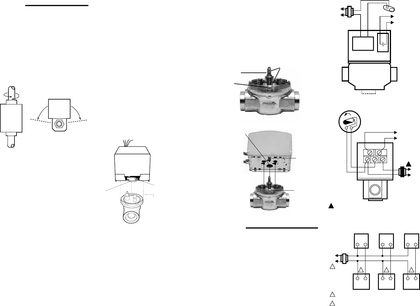
TO INSTALL REPLACEMENT ACTUATOR
ON THE VALVE BODY
1.
Align the parallel flat surfaces in
double-D shaft of valve body with
notch in side of body (i.e. 90
°
to water
flow.) See Fig. 4.
This makes actuator
attachment easier.
2. Wiring connections may be made either
before or after actuator installed on
valve body.
3.
Place the manual lever on the
actuator in the MAN. OPEN position.
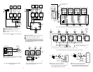
WIRING
Disconnect the power supply before
connecting wiring to prevent electrical shock
or equipment damage.
All wiring must comply with local codes and
ordinances. Connections to the individual
valves are shown in Fig. 6 and 7. See Fig. 8
through 14 for typical hookups.
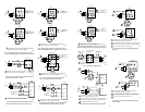
If replacing a Taco, Dole, Flair or White
Rodgers 3-wire valve with a 2-wire V8043E or
F, see Fig. 15 through 27. Check that the
pressure rating of the new valve is
appropriate for the application.
R
L1
(HOT)
L2
1
1
POWER SUPPLY. PROVIDE DISCONNECT MEANS AND
OVERLOAD PROTECTION AS REQUIRED.
END SWITCH
TO CIRCULATOR
OR ANOTHER
VALVE
TH
TR
24V
TRANSFORMER
THERMOSTAT
(TYPICALLY T87F)
TH TR
M5952
AUXILIARY
SWITCH
MOTOR
YELLOW
LEADS
TO CIRCULATOR
OR ANOTHER VALVE
RED LEADS
THERMOSTAT
(TYPICALLY T87F)TO
LINE
M5953
Fig. 6 - Typical wiring for V8043E, V8044E.
Fig. 7 - Typical wiring for V8043F.
L1
(HOT)
L2
1
1
2
2
2 2
POWER SUPPLY. PROVIDE DISCONNECT MEANS AND OVERLOAD
PROTECTION AS REQUIRED.
CONNECT V8043A BLACK LEADWIRE TO THERMOSTAT.
T822 T822 T822
V8043A V8043A V8043A
M10168
Fig. 8 - T822 Thermostat, V8043A valve hookup.
4. Line up motor coupling to the parallel flat
surfaces in double-D shaft of body and fit
the actuator onto the valve body,
ensuring that the shaft seats correctly.
(See Fig. 5)
5. Snap actuator onto body by pressing
down.
6.The manual lever may be released
manually, but it is also automatically
released when the valve is operated
electrically.
Fig. 5 - Installing Actuator
Notch Tab
Notch
Actuator
Coupling
Fig. 4 - Shaft Position
Double-D
Shaft
Parallel flat surfaces
align with Notch on
side of valve body
Notch