2004.09 Printed in Canada
Form No. 95C-10932
APPLICATION
These valves consist of a motorized
actuator and valve assembly for controlling
the flow of hot water to a heat exchanger
such as a radiator, convector, finned
baseboard radiator, or infloor radiant coil
for space temperature control. The V8043
5000 series valves provide two-position,
straight through control of supply water at
up to 300 psi operating pressure.
Quick Fit actuator provides easy snap on and
off connection to the valve assembly.
SPECIFICATION
Actuator Electrical Rating:
24Vac 60 Hz, 0.30 A Current Draw,
5 W, 7.2 VA maximum
Electrical Connection:
18” leads or screw terminal board
Auxiliary Switch Rating:
120V, 4.4A running, 26.4A Inrush (60 Hz);
50 VA Pilot duty at 24 V.
Fluid Temperature:
Standard models (class F motor):
200° F (93° C) Max.
Ambient Temperature:
125°F (52° C) Max.
Humidity Limits:
95% Relative Humidity, Non-condensing
Shipping and Storage Temperature:
-40°F to 150°F (-40°C to 65°C).
Atmosphere:
Non-corrosive, non explosive.
Maximum Soldering Temperature:
500°F (260°C). Rubber ball plug must be
moved away from the seat for soldering.
Maximum System Pressure Rating:
300 psi (2000 kPa), PN20.
Flow Characteristics:
Quick opening for on-off application.
Slow return for water hammer resist.
Maximum Close-off Rating (@ Flow
Capacity Rating) :
20 psi (@ 3.5 Cv)
8 psi (@ 8 Cv)
Actuator Materials:
Case:galvanized steel.
Cover : zinc plated steel.
Sector gear: Brass
Valve Material:
Body of forged brass; drive shaft stem of
stainless steel; ball plug of Buna-N rubber;
o-ring seals of EPDM rubber.
Service Medium:
Suitable for glycol/water mix up to 50:50
use in closed hydronic systems. Not for
use with oxygenated water, potable water
or steam.
Use this valve in hydronic systems which
do not contain dissolved oxygen in the
system water. The dissolved oxygen,
which is found in systems that have a
frequent source of make-up water, causes
the rubber plug inside the valve to
deteriorate and eventually fail.
Approvals:
CSA C/US Certified to Canadian Standards
Association and Underwriter's Laboratories
Standards.
MODELS
V8043 (Straight through, Normally Closed)
V8043A: Leadwires
V8043E: Leadwires and End Switch
V8043F: Terminal Board and End Switch
2
V8043A,E,F 5000 Series
ZONE VALVES
1
Patent Pending
CAUTION
1. Disconnect power supply before
connecting wiring to prevent electrical
shock or equipment damage.
2. Normally it is not necessary to remove
the actuator from the valve body during
installation. If the valve must be
disassembled, be certain that it is
reassembled with the water flow in the
direction of the arrow. Reversal of the
actuator results in damage to the gear
train.
3. On 24V systems, never jumper the
valve coil terminals even temporarily.
This can burn out the heat anticipator in
the thermostat.
INSTALLATION
When Installing this Product…
1. Read these instructions carefully. Failure
to follow them could damage the product
or cause a hazardous condition.
2. Check the ratings given in the
instructions and on the product to make
sure the product is suitable for your
application.
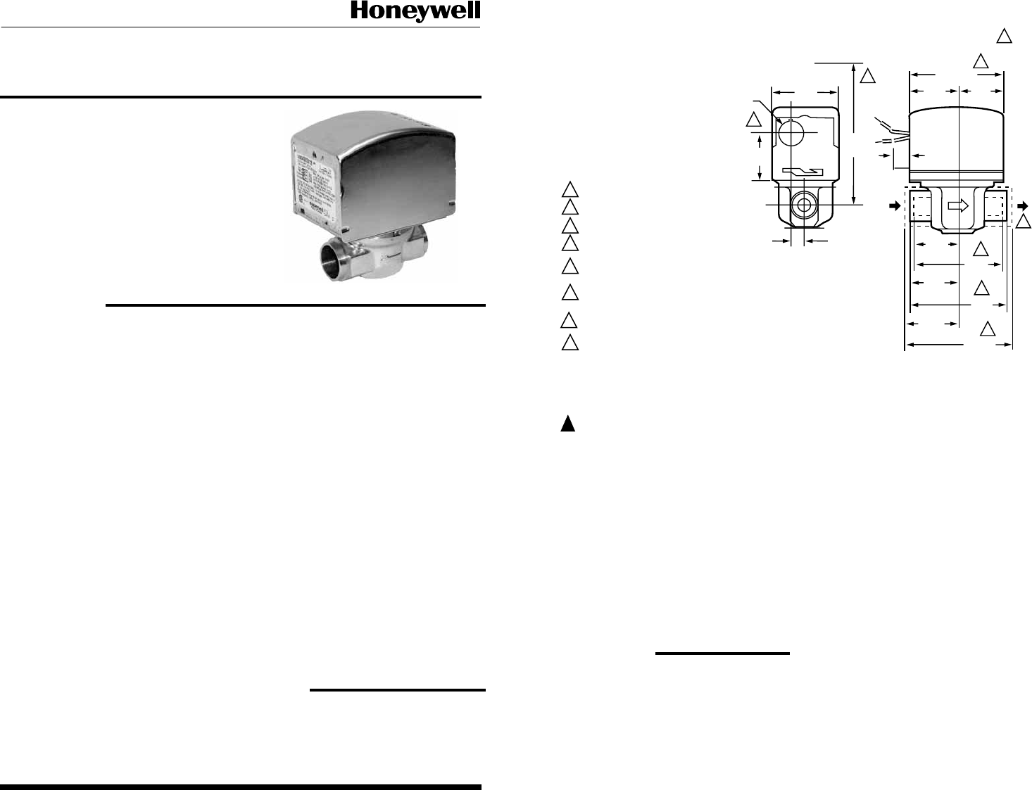
Fig. 1 - Mounting Dimensions in in. (mm in Brackets)
3. Installer must be a trained, experienced
service technician.
4. After installation is complete, check out
product operation as provided in these
instructions.
Location
Install the valve in an area with adequate
clearance to:
- Move the manual opening lever on the
side of the actuator
- Remove the actuator cover
- Wire the actuator
- Replace the actuator motor
The valve location should be in an area
where the temperature does not exceed the
maximum valve operating ambient
temperature and fluid temperatuare.
Manual Lever
The V8043 normally closed valves can be
opened manually by moving the manual lever
slowly and firmly to the MAN. OPEN position
and pushing up to the stop. The stop permits
the valve to be locked in the open position.
The valve returns to automatic position when
it is energized.
HEIGHT NEEDED TO REMOVE COVER.
DIMENSIONS FOR 1/2 IN. COPPER TUBING.
DIMENSIONS FOR 3/4 IN COPPER TUBING.
DIMENSIONS FOR 1 IN. COPPER TUBING.
4-7/8 IN. (124) MAX ON V8034F WITH TERMINAL
BOARD ENCLOSURE.
V4034B AND V8043B VALVES THAT ARE
NORMALLY OPEN IN THE DE-ENERGIZED
POSITION HAVE NO MANUAL LEVER.
REFER TO MOUNTING INSTRUCTIONS.
OPENING FOR 1/2 IN. CONDUIT ON MANUAL
LEVER SIDE FOR V4043, V8043.
1
2
3
4
5
6
7
8
M10175.A4
AUTO
MAN OPEN
AB
8
1
6
5
2
3
4
V4043, V8043 SWEAT COPPER CONNECTION MODELS
2-3/8
(60)
7/8 DIA.
(22)
1-1/2
(38)
5-1/4
(133)
15/32
(12)
IN
OUT
3-1/2 (89)
1-3/4
(44)
3/8
(10)
1-3/4
(44)
1-5/16
(33)
1-3/8
(35)
2-5/8
(66)
2-3/4
(70)
1-11/16
(43)
3-3/8
(86)
7


