


V4943/V8943B,C,N; V4944/V8944B,C,L,N REGULATING DIAPHRAGM GAS VALVES
65-0214—08 10
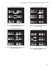
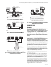
Operation of the V4943B,C,N/
V8943B,N
The V4943/V8943B,C,N Valves are combination gas controls
that include a single stage of pressure regulation in addition to
the shut-off function. They have a single solenoid and a single
regulating diaphragm.
When the controller is not calling for heat, the valve solenoid
coil is not energized. Static gas inlet pressure and a spring act
together to close the valve. In this condition, a three-way servo
valve directs inlet pressure directly above the main diaphragm,
creating static pressure on both sides of the main diaphragm.
On a call for heat, the controller contacts close and the valve
solenoid coil is energized, opening the servo valve and
allowing the gas that is above the main diaphragm to bleed
downstream, and diverting inlet (supply) gas through a supply
orifice. This reduces the pressure above the diaphragm, and
the gas that is bled off flows through a regulating valve to the
outlet of the gas valve. The pressure differential across the
main diaphragm is greater than the spring force, so the valve
opens. The valve opening rate is controlled by a timing orifice
through which the bleed gas passes.
Once the valve is open, outlet pressure is sensed through the
bleed passage. The outlet pressure acts on the regulating
(servo) diaphragm and tends to open or close the integral
regulating valve until a force balance is established between
the outlet pressure acting on the servo diaphragm and the
regulator spring that acts on the atmospheric side of the servo
diaphragm.
The system is balanced when the flow of supply gas through
the supply orifice is equal to the outflow of gas through the
regulating valve. The regulated output pressure required to
achieve equilibrium is varied by increasing or decreasing the
spring force acting on the atmospheric side of the regulating
diaphragm. Pressure adjustment is done through the use of a
threaded nylon screw acting on the regulating spring.
Regulator springs with different spring rates provide the
various ranges of pressure regulation needed for natural and
LP gases.
After the controller is satisfied, the procedure is reversed. The
controller contacts open and the solenoid coil is de-energized.
The plunger is released, moving to the down position. The
servo valve closes, diverting supply gas away from the orifice
and allowing the gas inlet pressure to act directly above the
main diaphragm. The resulting increase in upper chamber
pressure, along with the main spring, forces the main
diaphragm against the valve seat, stopping the gas flow.
In the event of a power failure during automatic operation of the
valve, the V4943/V8943B,C,L,N Valve servo valve closes,
diverting supply gas away from the orifice and allowing the gas
inlet pressure to act directly on the main diaphragm. The
change in upper chamber pressure, along with the main
spring, forces the main diaphragm against the valve seat,
stopping the gas flow. Normal operation will resume upon the
restoration of power.
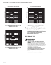
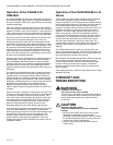
Operation of the V4944/V8944B,C,L,N
Valves
These models use two pressure regulators (low fire and high
fire) and two solenoids to provide two distinct stages of
pressure regulation. The first stage pressure regulator solenoid
activates the same quick-close orifice valve and servo valve as
in the V4943/V8943 models, but the bleed gas now flows
through a first stage (low fire) regulator valve to the outlet. This
maintains the outlet at a pressure controlled by the low fire
regulator. The second stage regulator (high fire) is set to a
higher outlet pressure. When the second stage solenoid is
energized, gas is shunted past the low fire regulator through a
timing orifice. The increased flow of supply gas (due to the
second servo valve opening) further reduces the pressure
above the main diaphragm, causing it to open more. The
corresponding increase in outlet pressure forces the low fire
regulator closed, and the valve regulates off the high fire
regulator.
The V4944/V8944L and N models use a timing orifice that
gives an opening time to low fire of less than six seconds. The
slower opening V4944/V8944B and C use timing orifices that
give an opening time of three to 25 seconds.
Both regulators can be adjusted separately and the springs are
sized so that the highest achievable pressure of the low
pressure regulator range is less than the lowest achievable
pressure of the high fire pressure regulator. The high fire
setpoint cannot be achieved without the first stage solenoid
being energized.
Valve closing operation is identical to that described for V4943/
V8943B,C,N valves.
CHECKOUT AND
TROUBLESHOOTING
WARNING
Explosion or Fire Hazard.
Can cause serious injury or death.
Do not let fuel accumulate in the combustion chamber.
If fuel is allowed to enter the chamber for longer than a
few seconds without igniting, an explosive mixture
could result.
CAUTION
Equipment Damage Hazard.
Failure to complete tests can cause equipment
damage.
1. Do not put the system into service until you have
satisfactorily completed all applicable tests
described in the Checkout section of the instructions
for the flame safeguard control, and any other tests
required by the burner manufacturer.
2. Close all manual fuel shutoff valves as soon as
trouble occurs.