


2
8. Level the thermostat exactly using a spirit level or
plumb line. Tighten the mounting screws.
IMPORTANT: An incorrectly leveled thermostat will
cause the temperature control to deviate from setpoint.
9. Replace the thermostat cover
Settings and Adjustments
TEMPERATURE SETTING
Move the temperature setting lever to the desired control
point on the temperature scale. On positive off models, the
control circuit is broken when the lever is moved to the
extreme low end of the temperature scale. On models with
temperature range stops, temperature setting lever can be
moved only between the two temperature range stops.
HEAT ANTICIPATOR SETTING (T822D Only)
IMPORTANT: This thermostat has an adjustable heat
anticipator and will operate properly ONLY IF THE
ANTICIPATOR IS ADJUSTED TO MATCH THE
CURRENT DRAW OF THE PRIMARY CONTROL.
Use this thermostat only on systems with current
draws that fall within the range of the heat anticipator.
Do not use device on Powerpile (millivolt) Systems.
A current rating is usually stamped in the nameplate of
the primary control. Set the adjustable heat anticipator
indicator to match the value given on the nameplate.
If current rating is not available, proceed as follows to
determine the rating:
1. Turn off power.
2. Wire thermostat, except for connection to W termi-
nal, but do not mount it on the wall.
3. Connect ammeter between W wire and W terminal
on the thermostat.
4. Prepare the system for operation.
5. Turn on power.
6. Turn system switch to heat.
7. Increase thermostat setpoint as necessary to get sys-
tem operating.
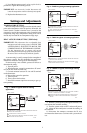
Fig. 2—T822D in typical gas heating application.
POWER SUPPLY. PROVIDE DISCONNECT MEANS AND OVERLOAD
PROTECTION AS REQUIRED.
T822D, T8022D ADJUSTABLE HEAT ANTICIPATOR. T822A HAS A
FIXED HEAT ANTICIPATOR.
M1183A
T822A,D; T8022D
1
1
L1
(HOT)
L2
R
TEMP. FALL
W
H1
H1
ANTICIPATOR
GAS
CONTROL
2
2
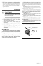
Fig. 3—T822D in typical oil heating application.
POWER SUPPLY. PROVIDE DISCONNECT MEANS AND OVERLOAD
PROTECTION AS REQUIRED.
T822D, T8022D ADJUSTABLE HEAT ANTICIPATOR SHOWN. T822A
HAS A FIXED HEAT ANTICIPATOR.
M1184A
T822A,D; T8022D
1
1
L1
(HOT)
L2
R
TEMP. FALL
W
H1
H1
ANTICIPATOR
OIL
PRIMARY
T
T
2
2
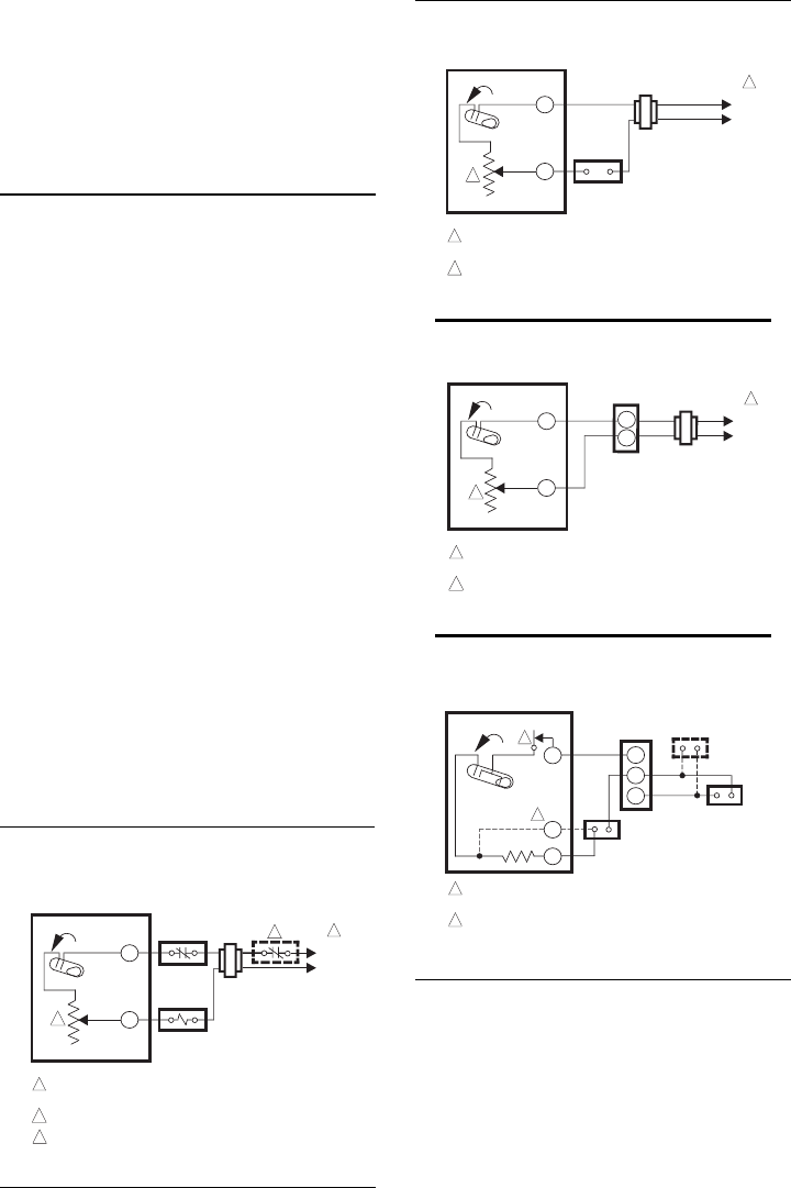
Fig. 4—TS822A in typical millivoltage heating
application.
2
CONNECT R AND W TERMINALS FOR 750 mV SYSTEMS. CONNECT
R AND Y TERMINALS FOR 250/500 mV SYSTEMS.
POSITIVE OFF SWITCH PROVIDES COMPLETE CONTROL CIRCUIT
SHUTOFF. DOES NOT REPLACE POWER SUPPLY DISCONNECT
SWITCH.
M1311
TS822A
TEMP. FALL
H1
R
Y
1
W
LIMIT
CONTROL
1
TH
TH/
PP
PP
MILLIVOLTAGE
GENERATOR
MILLIVOLTAGE
GAS CONTROL
PILOTSTAT
CONTROL
(IF USED)
2
8. With the system operating through the ammeter, wait
one minute, then read the ammeter.
9. Turn the system switch to OFF, and turn off power.
10. Adjust the heat anticipator to match the reading on
the ammeter.
11. Disconnect the ammeter, reconnect the W wire,
and mount the thermostat. Continue with system check-
out.
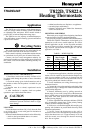
Fig. 1—T822D in typical electric heating
application.
3
3
POWER SUPPLY. PROVIDE DISCONNECT MEANS AND OVERLOAD
PROTECTION AS REQUIRED.
ALTERNATE LIMIT CONTROL LOCATION.
T822D, T8022D ADJUSTABLE HEAT ANTICIPATOR SHOWN. T822A
HAS A FIXED HEAT ANTICIPATOR.
M1164B
T822A,D; T8022D
1
1
L1
(HOT)
L2
LIMIT
CONTROL
R
TEMP. FALL
W
H1
2
H1
ANTICIPATOR
ELECTRIC
HEAT RELAY
2