


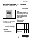
ZIO
®
/ZIO PLUS LCD WALL MODULES
63-1322—02 2
SPECIFICATIONS
Compatibility: Full feature set, including scheduling and
password protection requires the latest Spyder firmware
(field upgradeable with Spyder Flash Tool), Spyder Tool
version greater than 5.18, and WEBs-AX Workbench ver-
sion 3.4.57 or greater.
Construction: Two-piece construction, cover and internally
wired subbase. Field wiring, 18 to 24 AWG (0.82 to 0.20
sq. mm), connects to a terminal block in the subbase.
Mounting Options: The LCD wall modules can be mounted
on a standard two by four inch junction box or on a 60 mm
diameter junction box. The modules may be mounted up to
200 ft. (61 m) from the programmable controller. Twisted
pair wiring is recommended for distances longer than 100
ft. (30.5 m).
Dimensions (H/W/D): See Fig. 2 on page 2.
Environmental Ratings:
Operating Temperature: 30°F to 110°F (-1°C to 43°C)
Shipping Temperature: -40°F to 150°F (-40°C to 65.5°C)
Relative Humidity: 5% to 95% non-condensing
Temperature Setpoint Range: Default range is 55°F to 85°F
(10°C to 35°C); configurable for other ranges.
Temperature Sensor Accuracy: ±0.36°F at 77°F (±0.2°C at
25°C)
Humidity Sensor Accuracy (TR71-H/TR75-H only): ±5%
RH from 20% to 80% RH
Power: 18 Vdc power is supplied to the wall module from the
2-wire S-BUS connection to the programmable
controller.
Accessories: 50007298-001 (pack of 12) medium, cover
plate; 6-7/8 x 5 in. (175 x 127 mm).
Approvals:
CE; UL94-HB plastic enclosure; FCC Part 15,
Class B
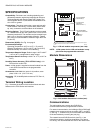
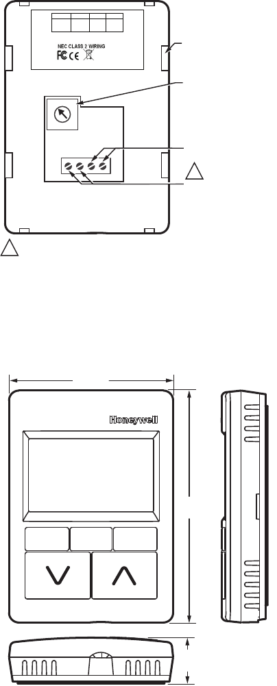
Terminal Wiring Location
Fig. 1 illustrates the location of the terminal block and other
features on the TR70 Series wall modules.
Fig. 1. LCD wall module components (rear view).
NOTE: 18 Vdc power for the LCD wall modules is sup-
plied from the programmable controller.
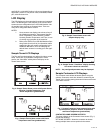
Module Dimensions
Fig. 2. Wall module dimensions in inches (mm).
Communications
The wall modules use a sensor bus (S-BUS) for
communications with the programmable controller.
For network communication, the building’s LON or BACnet®
network wires connect to the two terminals (NET-1 and NET-
2). See Fig. 1. A network bus port is accessible at the bottom
of the wall module by removing the jack plug.
The network bus and S-BUS terminals (see Fig. 1) are
insensitive to polarity, minimizing installation errors due to
mis-wiring. The recommended wire size for the network bus
M27349
SLOTS FOR SUBBASE
LOCKING TABS (X4)
0
1
2
3
4
9
8
7
6
5
WALL MODULE BUS
ADDRESS DIAL
(DEFAULT SETTING = 1)
S-BUS PROGRAMMABLE
CONTROLLER CONNECTION
NETWORK BUS
CONNECTION
EACH OF THE TWO WIRE CONNECTIONS FOR THE S-BUS AND NETWORK
BUS TERMINALS ARE POLARITY INSENSITIVE.
1 2 3 4
1
1
50028668-XXX
4321
S-BUS
S-BUS
NET-2
(optional)
NET-1
(optional)
TR70-H
YY WK
HONEYWELL
PATENT PENDING
GOLDEN VALLEY,MN
ASSEMBLED IN MEXICO
3 5/16 (84)
4 5/8
(117)
15/16
(24)
M27347