


VisionPRO
TM
TH8000 Series
3
69-2693—01
ENGLISH
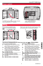
NOT
USED
MCR29483
NOT
USED
MCR29482
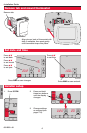
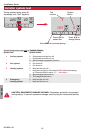
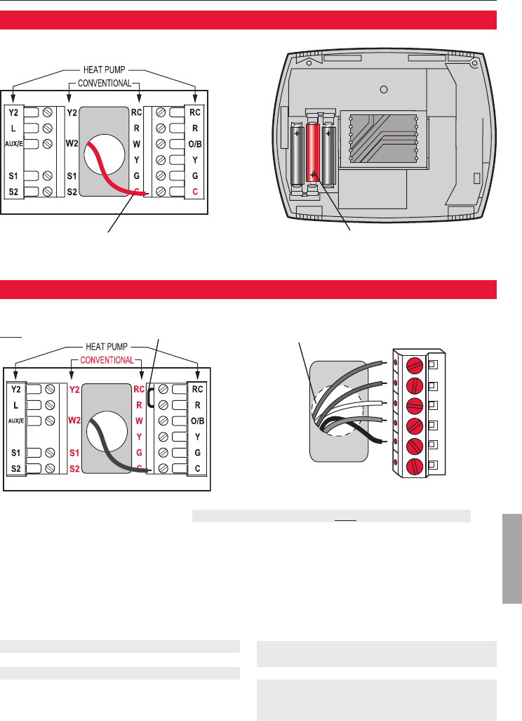
For24VACprimarypower,connectcommon
sideoftransformerto“C”terminal.
Insert supplied batteries for
primary or backup power.
Power options
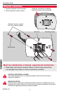
Push excess wire back into the wall opening. Plug
wall opening with non-flammable insulation.
Remove factory-installed jumper
only for two-transformer systems.
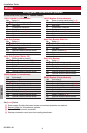
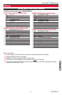
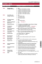
Conventional Terminal Letters:
R Heating power. Connect to secondary
side of heating system transformer.
Rc Cooling power. Connect to secondary
side of cooling system transformer.
C Common wire from secondary side of
cooling transformer (if 2 transformers).
W 1st stage heat relay.
W2 2nd stage heat relay.
Y 1st stage compressor contactor.
Y2 2nd stage compressor contactor.
G Fanrelay.
S1 Optional outdoor or remote sensor.
S2 Optional outdoor or remote sensor.
Heat Pump Terminal Letters:
R Heating power. Connect to secondary
side of heating system transformer.
Rc Cooling power. Connect to secondary
side of cooling system transformer.
C Common wire from secondary side of
cooling system transformer.
Y 1st stage compressor contactor.
Y2 2nd stage compressor contactor.
Aux/E
Auxiliary/Emergencyheatrelay.
G Fanrelay.
L Heat pump reset (powered continuously
whenSystemissettoEmHeat;system
monitorwhensettoHeat,CoolorOff).
O/B Changeover valve for heat pumps.
S1 Optional outdoor or remote sensor.
S2 Optional outdoor or remote sensor.
Terminal Designations Shaded areas below apply only to TH8320/TH8321.
Wiring