


Installation Guide
4
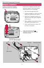
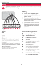
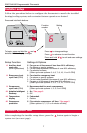
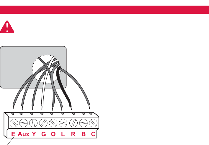
Wiring
1 Loosen screw terminals, insert
wires into terminal block, then re-
tighten screws.
2 Push excess wire back into the
wall opening. Keep wires in shaded
area as shown at left.
3 Plug the wall opening with non-
flammable insulation to prevent
drafts from affecting thermostat
operation.
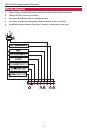
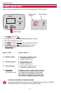
Terminal Designations
EE
Emergency heat relay.
AAuuxx
Auxiliary heat relay.
YY
Compressor contactor.
GG
Fan relay.
OO
Heat pump changeover valve
energized in cooling.
LL
Heat pump reset.
RR
Power wire from secondary
side of system transformer.
BB
Heat pump changeover valve
energized in heating.
CC
Common wire from secondary
side of system transformer.
Terminal
block
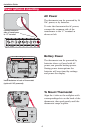
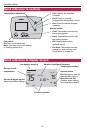
NOTES
C terminal
The C (common wire) terminal is optional
when thermostat is powered by batteries.
L terminal
Heat pump reset. L terminal is powered con-
tinuously when thermostat is set to Em Heat.
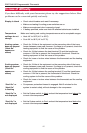
Wire specifications
Use 18- to 22-gauge thermostat wire.
Shielded cable is not required.
Keep wires in this
shaded area
CAUTION: ELECTRICAL HAZARD. Can cause electrical shock or equipment damage.
Disconnect power before wiring.
Wiring