


TG509, TG510, TG511, TG512 VERSAGUARD™ UNIVERSAL THERMOSTAT GUARDS
68-0104—4
6
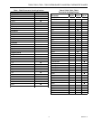
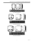
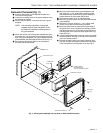
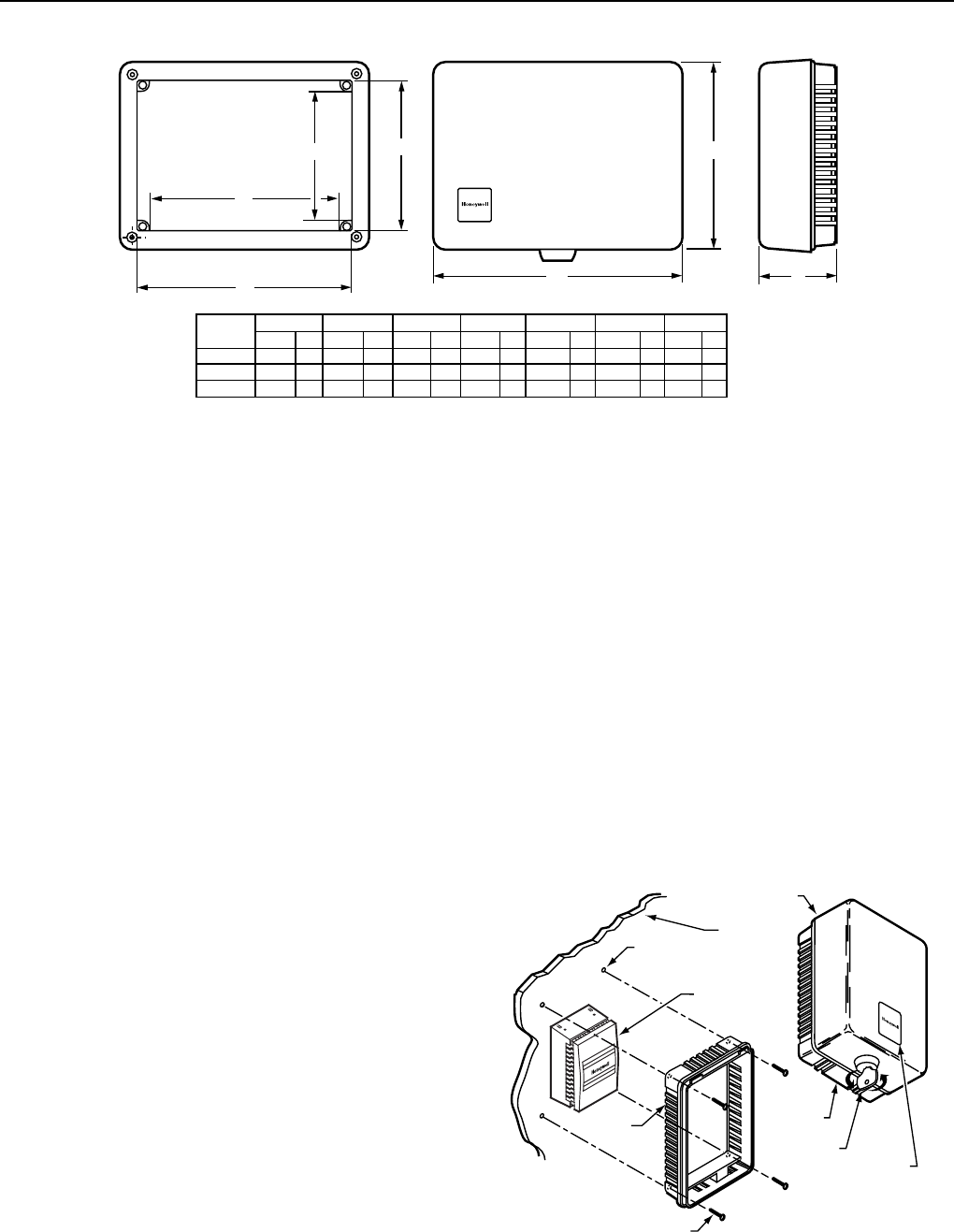
Fig. 4. TG512 overall dimensions.
E
F
TG512A
TG512B
TG512D
8-3/8
8-3/8
8-3/8
213
213
213
5-7/8
5-7/8
5-7/8
149
149
149
9-3/4
9-3/4
9-5/8
248
248
244
7-1/4
7-1/4
7-1/8
184
184
180
3-3/8
3-3/8
3-1/4
86
86
83
MODEL
NUMBER
IN. IN. IN. IN. IN.MM MM MM MM MM
E
ADFG
M644C
FRONT VIEW
SIDE VIEW
G
A
D
RING BASE ONLY
B
C
7-3/8
7-3/8
7-3/8
187
187
187
4-7/8
4-7/8
4-7/8
124
124
124
IN. IN.
MM
MM
CB
INSTALLATION
When Installing this Product…
1. Read these instructions carefully. Failure to follow them
could damage the product.
2. Check the dimensions given in the instructions and on
the product to make sure the product is suitable for your
application.
The Versaguard™ Universal Thermostat Guards can be used
in new or existing thermostat applications. In existing
thermostat applications, the guard can be installed without
removing the thermostat from the wall. In these applications,
the thermostat guard is used without the solid wallplate (only
ring base and cover are used). In new thermostat
applications, the guard can be used with or without the solid
wallplate. The wallplate is typically used to cover mounting
marks from the old thermostat.
Refer to the following sections for specific mounting
procedures for thermostat guard applications.
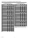
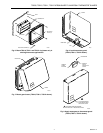
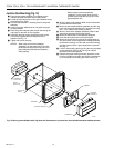
Mount Thermostat Guard Without Wallplate
(Fig. 5 and 6)
³ Place the ring base over the thermostat (and wallplate,
subbase or adaptor plate) on the wall.
· Align the ring base with the thermostat and level
approximately.
» Mark the four mounting holes.
NOTE: Do not use the four brass screws for mounting
the TG509. The brass screws are intended for
models with wallplates only.
¿ Mount the ring base on the wall using the four no. 6
sheet metal screws and four anchors provided as
shown in Fig. 5 for the TG509 and Fig. 6 for the FG510,
TG511 and TG512.
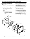
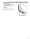
´ Mount the guard cover by placing the hinged edge of
the guard cover on the ring base and swinging it down
(horizontal mounting) or to the side (vertical mounting)
until the guard cover is in place against the ring base.
See Fig. 7.
² Lock the thermostat guard by turning the key (provided)
counterclockwise. See Fig. 8. The key can be removed
only in the locked position.
¶ Remove the paper backing and clear protective cover
from the included monogram and place the monogram
in the recessed area on the guard cover. See Fig. 9.
NOTE: The TG509F,G Thermostat Versaguards™ are
shipped with an allen wrench secured in the
top notch of the ring base. When thermostat
calibration is needed, remove the Versaguard
cover and use the wrench to remove the top
two allen screws in the thermostat cover. This
allows servicing of the thermostat while the
ring base is in place.
THERMOSTAT
WALL
RING BASE
MOUNTING
HOLES (4)
MOUNTING SCREWS (4)
6
0
6
0
7
0
8
0
9
0
6
0
7
0
8
0
9
0
RING
BASE
KEY
M15014
RECESSED AREA
FOR MONOGRAM
COVER
FRONT OF DEVICE
MOUNTING RING BASE
Fig. 5. Mount TG509 ring base only in existing thermostat
applications. TG509 guard cover, lock, monogram area.