


TB7220 ULTRASTAT PROGRAMMABLE THERMOSTAT
63-2636—03 6
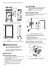
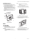
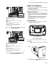
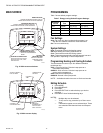
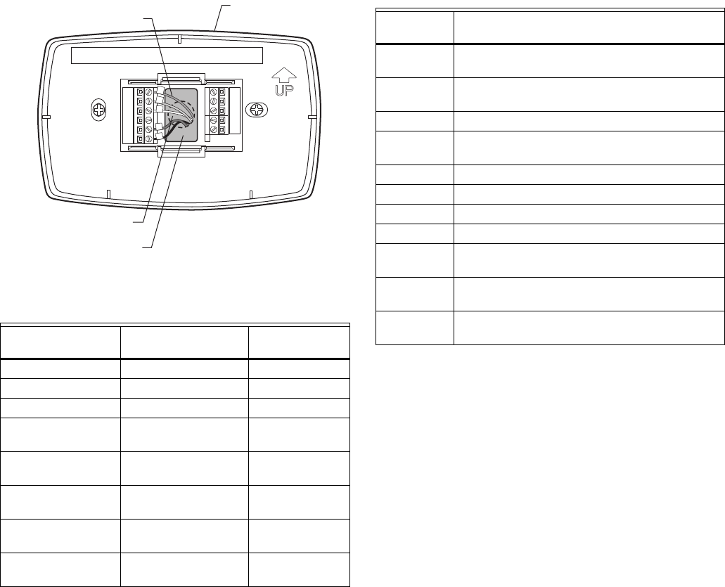
Fig. 11. Restrict wires to shaded area of wire hole.
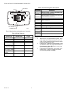
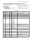
Table 4. Wiring Diagrams.
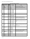
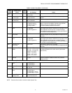
Table 5. Terminal Designation Descriptions.
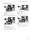
NOTES:
1. When used in a single-transformer system, leave
metal jumper wire in place between Rc and R. If
used on a two-transformer system, remove metal
jumper wire between Rc and R.
2. Common wire is optional when thermostat is used
with batteries. When using separate transformers
for heating and cooling, the common must come
from the cooling transformer.
3. If thermostat is configured for a heat pump in the
Installer Setup, configure changeover valve for
cool (O-factory setting) or heat (B).
System Type
Wallplate Terminal
Identifications
Wiring Diagram
Figure
Standard Heat/Cool Conventional 12, 13
Heat Only Conventional 14
Cool only Conventional 15
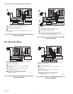
Standard Multistage
up to 2 Heat/2 Cool
Conventional 16, 17
Heat Pump
(No Auxiliary Heat)
Heat Pump 18, 19
Heat Pump
(with Auxiliary Heat)
Heat Pump 20, 21
Multiple T7770A
Sensors
— 26, 27, 28
Multiple C7189U
Sensors
—29
WALLPLATE
M22266
WALL OPENING
WIRE
SHADED AREA
Terminal
Designation Description
Rc
(see Note 1)
Power for cooling—connect to secondary side
of cooling system transformer.
R
(see Note 1)
Power for heating—connect to secondary side
of heating system transformer.
Y Compressor output.
C
(see Note 2)
Common wire from secondary side of cooling
system transformer.
W Heat relay.
GFan relay.
W2 Second stage heat relay.
Y2 Second stage cooling.
O/B
(see Note 3)
Changeover valve for heat pumps.
S1
(See Note 5)
Optional outdoor or indoor remote sensor.
S2
(See Note 5)
Optional outdoor or indoor remote sensor.