


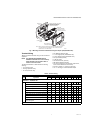

TB6575/TB8575 DIGITAL FAN COIL THERMOSTATS
13 62-0311—13
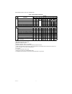
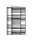
10 Control Method for
4-Pipe Auto
Changeover
1 Single Setpoint (Default) Uses switching differential
to change between heating
and cooling and controls to
a single setpoint (Only
displayed for system types
5 or 7)
2 Heat and Cool Setpoints (2 setpoint method) Uses a deadband of no
control and controls to a
heat or cool setpoint. (Only
displayed for system types
5 or 7)
10.5 Deadband for Heat/
Cool Setpoints
2 to 9 Range is 2 to 9. Default is 3. Deadband = minimum
distance between heating and cooling setpoints.
Available when Heat and
Cool Setpoints are chosen
for the control method for 4-
pipe Auto (IS 10)
Switching
Differential for
Single Setpoint
2 to 6 Range is 2 to 6. Default is 3. Heat switching point =
setpoint - switching differential. Cool switching point
= setpoint + switching differential.
Available when Single
Setpoint is chosen for the
control method for 4-pipe
Auto (IS 10)
11 CPH Value for Heat 1 to 12 Range is 1 to 12. Default is 4. The number selected
indicates the maximum
times Heating is cycled on
per hour (CPH). IS 2
selection is 5.
12 CPH Value for Cool 1 to 6 Range is 1 to 6. Default is 3. The number selected
indicates the maximum
times Cooling is cycled on
per hour (CPH).
13 CPH for Auxiliary
Electrical Heater
1 to 12 Range is 1 to 12. Default is 6. The number selected
indicates the maximum
times Auxiliary Heating is
cycled on per hour (CPH).
14 Display
Temperature
Adjustment
-4 to 4 Range is -4°F to +4°F; Default is 0°F.
15 Temperature
Display Mode
0 Display Room Temperature
1 Display Setpoint
2 Display Temperature and Setpoint; Default.
16 Setpoint Range
Stop for Heating
50 to
90
Range is 50°F to 90°F. Default is 90°F.
17 Setpoint Range
Stop for Cooling
50 to
90
Range is 50°F to 90°F. Default is 50°F.
18 Keypad Lockout 0 All keys are available (Default)
1 The System button (Heat/Cool) is locked out
2 Both the System and Fan buttons are locked out.
3 All buttons are locked out (System, Fan, Up Arrow,
and Down Arrow). The LCD displays LOCKED.
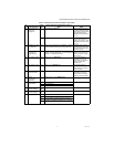
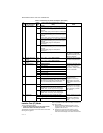
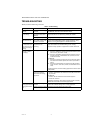
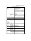
Table 4. Installer Setup (IS) Codes and Options. (Continued)
IS
Code Code Description
Option
Value
Option Description (Default value shown in
Bold) Notes