


TB6575/TB8575 SUITEPRO™ DIGITAL FAN COIL THERMOSTATS
9 62-0278—07
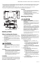
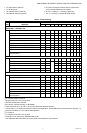
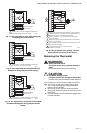
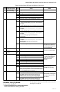
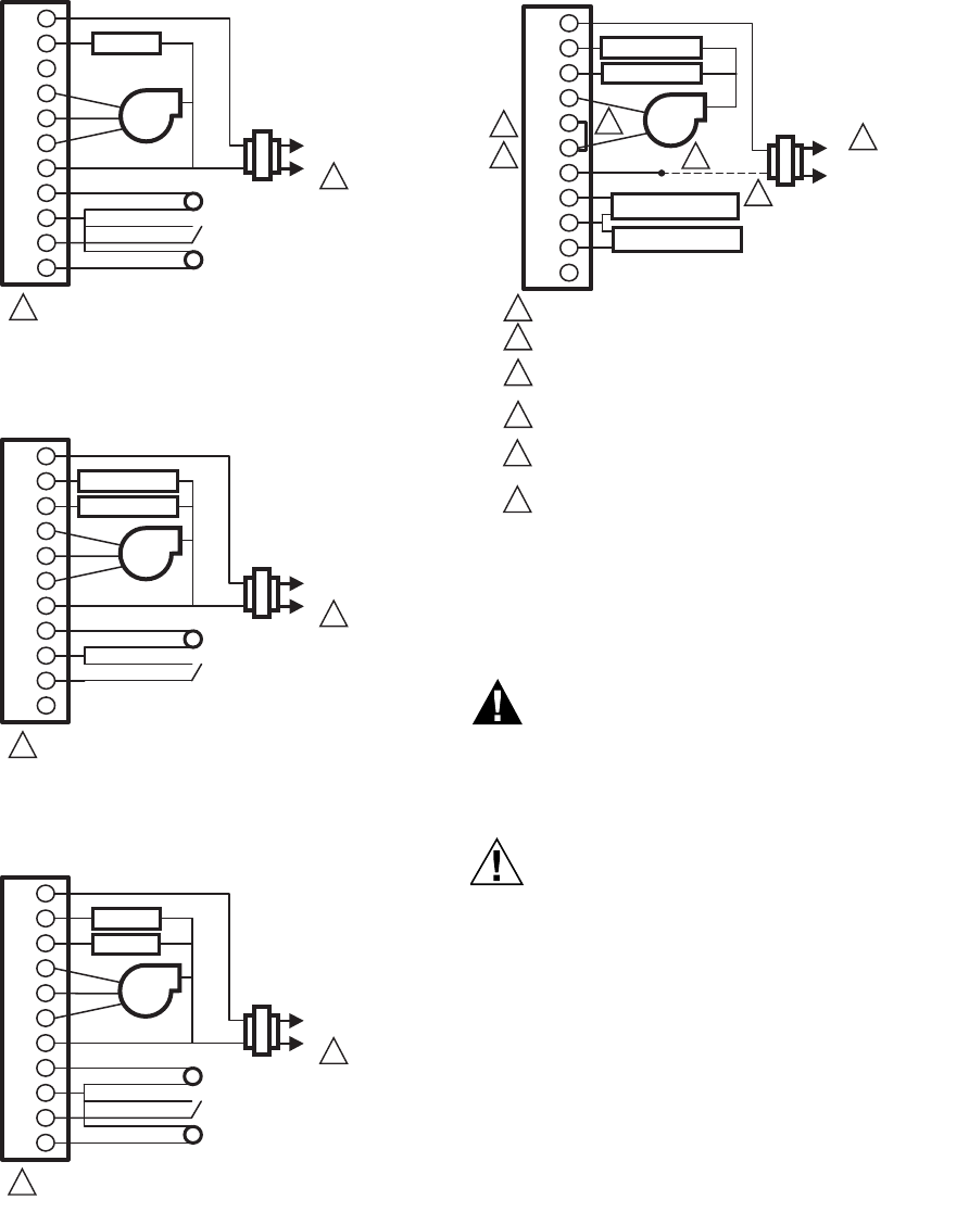
Fig. 17. Two pipes (Heat or Cool) auto changeover
wiring diagram (24 Vac shown).
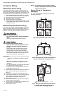
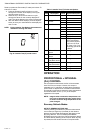
Fig. 18. Four pipes (Heat and Cool) Manual/Auto
Changeover wiring diagram (24 Vac shown).
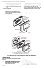
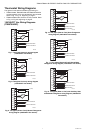
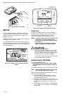
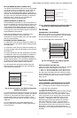
Fig. 19. Two pipes (Heat or Cool) with Auxiliary Heat
and Manual Changeover wiring diagram (24 Vac
shown).
.
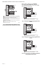
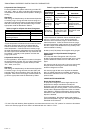
Fig. 20. Wiring diagram when missing a wire for
electromechanical retrofit (24 Vac shown).
Removing the Thermostat
WARNING
Risk of electrical shock.
Can cause severe injury, property damage or
death.
Disconnect power supply before servicing.
CAUTION
Equipment damage hazard.
Improper removal can damage the thermostat.
Carefully follow the thermostat removal directions.
If it is necessary to remove the thermostat from the sub-
base, refer to Fig. 21 and perform the following steps:
1. Turn off the thermostat by pressing the system
button until OFF displays.
2. Remove the power source from the thermostat.
3. Remove the small safety screw at the bottom of the
thermostat.
4. Use both hands to pull the thermostat straight away
from the sub-base.
24 VAC
M27576
VALVE
FAN
L1
(HOT)
L2
1
REMOTE SENSOR
REMOTE SETBACK
1
POWER SUPPLY. PROVIDE DISCONNECT MEANS AND
OVERLOAD PROTECTION AS REQUIRED.
PIPE SENSOR
R
W/Y
Y/A
GI
Gm
Gh
C
Rs
Sc
SB
Ps
24 VAC
M27577
HEAT VALVE
FAN
L1
(HOT)
L2
1
REMOTE SENSOR
REMOTE SETBACK
1
POWER SUPPLY. PROVIDE DISCONNECT MEANS AND
OVERLOAD PROTECTION AS REQUIRED.
COOL VALVE
R
W/Y
Y/A
GI
Gm
Gh
C
Rs
Sc
SB
Ps
24 VAC
M27578
VALVE
FAN
L1
(HOT)
L2
1
REMOTE SENSOR
REMOTE SETBACK
1
POWER SUPPLY. PROVIDE DISCONNECT MEANS AND
OVERLOAD PROTECTION AS REQUIRED.
PIPE SENSOR
AUX
R
W/Y
Y/A
GI
Gm
Gh
C
Rs
Sc
SB
Ps
24 VAC
M31329
HEAT VALVE
FAN
COOL VALVE
REMOTE SETBACK
REMOTE SENSOR
L1
(HOT)
L2
5
3
4
1
2
1
2
REMOVE PRE-WIRED WIRE FROM TERMINAL 5 (MID FAN SPEED).
JUMPER TERMINALS 5 AND 6 (MID AND HIGH FAN SPEEDS). FAN
MEDIUM SETTING WILL OPERATE ON HIGH SPEED.
CONNECT TERMINAL 7 TO THE MID FAN SPEED WIRE FROM
PREVIOUS SYSTEM.
REWIRE THE PREVIOUS MID FAN SPEED WIRE TO THE NEUTRAL
CIRCUIT IN THE SYSTEM.
POWER SUPPLY. PROVIDE DISCONNECT MEANS AND OVERLOAD
PROTECTION AS REQUIRED.
CHANGE INSTALLER SETUP IS CODE 9 TO 2 FOR
2 SPEED FAN CONTROL.
3
4
5
6
6
L
W/Y
Y/A
GI
Gm
Gh
C
Rs
Sc
SB
Ps